I've been following the MH370 disappearance since it happened. With such a lack of confirmed information there have been a lot of interesting theories discussed on multiple forums (Whirlpool and PPRUNE are a couple of interesting ones).
As I have a knowledge in acoustics (I am an Analyst / Software Engineer for an underwater acoustics company and I specialise in tracking things with pingers fitted to them), I've been trying to spread facts when I know them and try and dispel myths.
Today I saw an interesting video from Sky News on a forum of the suspected MH370 pings recorded by ADV Ocean Shield using the SUBSALV Towed Pinger Locator TPL-25 (pinger audible 18 seconds in):
I thought I would see if I could glean any information from the audio in the publicly released video. In particular I was wanting to look at the inter-ping interval to see how steady it was to try and determine if the noise is man-made or natural (ie marine mammal noise).
The signal is quite noisy with ambient ship noise and other transients (scuffing of shoes on deck!) but a repeated click can be heard.
Process
- Extracted the audio from the Youtube video using a web-based MP3 extractor
- Opened the MP3 in Adobe Audition and trimmed the file to the time segment corresponding to good audio (start time 41.787s from beginning of file, duration 22.462 seconds)
- Bandpass filtered the audio between 2kHz and 10kHz to remove LF ambient noise (NOTE: the 'pinger' is audible at about 3.4kHz however it obviously has been demodulated down from the raw signal observed on the TPL-25 to bring into the audible range)
 |
| Filtered Time Domain Signal - Red ticks added at repeated 'ping' noise |
- A manual search of the waveform (zooming in tight where necessary) was performed to measure the start time of each ping transient to within a couple of wavelengths
Results
The detection times of the pings are listed in the table below along with some basic statistics.
Ping #
|
Time (s)
|
Interval
(s)
|
1
|
0.758
|
|
2
|
1.861
|
1.103
|
3
|
2.964
|
1.103
|
4
|
4.067
|
1.103
|
5
|
5.171
|
1.104
|
6
|
6.274
|
1.103
|
7
|
7.38
|
1.106
|
8
|
8.486
|
1.106
|
9
|
9.592
|
1.106
|
10
|
10.696
|
1.104
|
11
|
11.801
|
1.105
|
12
|
12.907
|
1.106
|
13
|
14.014
|
1.107
|
14
|
15.12
|
1.106
|
15
|
16.226
|
1.106
|
16
|
17.333
|
1.107
|
18
|
19.549
|
1.108
|
19
|
20.657
|
1.108
|
20
|
21.764
|
1.107
|
Mean
|
1.10544
|
|
Std Dev
|
0.00172
|
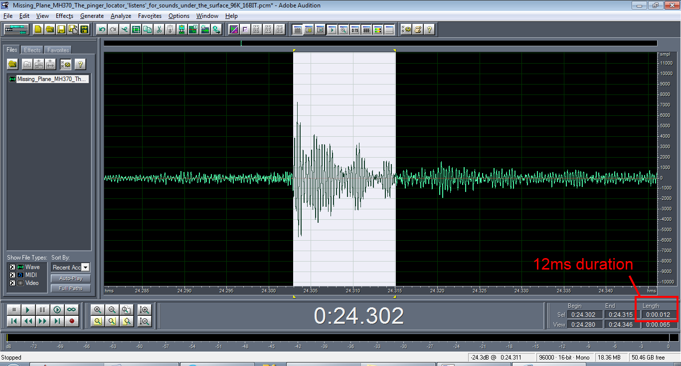 |
| Single Ping zoom view - Selected portion is 12ms duration |
This is incredibly stable over the 20 seconds that I've looked at and very unlikely to be a marine mammal (ie beaked or sperm whale) which DO create broadband pulses at regular intervals, but I've never seen them that regular.
This strongly suggests the recorded signal is man-made. The signal duration is consistently between 10 and 15 ms in duration. Highly probably it is from the Underwater Locator Beacon due to the very close match to the expected ping rate of 0.9Hz or 1 ping per 1.111 seconds, and the expected ping duration of 10ms.
However it COULD be from other repetitive signal sources such as a stray echo sounder nearby; although that would be a soul crushing disappointment to all onboard ADV Ocean Shield and the other involved in the search. Also.. WHAT CRAZY PERSON WOULD PUT A SOUNDER ON DURING AN ACOUSTIC SEARCH!?!
One last thing to note about the observed ping intervals is that they appear to increase slightly over time (order of 4ms). Whilst the sample set isn't long enough to show consistency, I see patterns like these all the time when tracking moving items fitted with pingers from stationary receivers (conceptually the same thing as the stationary pinger and moving receiver on ADV Ocean Shield).
It could be either:
- The decreasing battery voltage is causing the ping interval to increase. However it doesn't seem likely this phenomenon would be observed over such a short time window
- The audio recording segment corresponds to when the towed pinger locator has performed a Closest Point of Approach (CPA) and is now opening in range from the source. When this happens a effect similar to Doppler occurs in that the time between successive pings appears to increase as because between successive pings the receiver has moved further away.
For the segment analysed it corresponds to a slant range increase of 6 metres over 20 seconds, or 0.3m/s or 0.6 knots. If the towed pinger locator is transiting at 2 knots and the depth of the receiver is known, you could estimate a very rough range to the source by looking at the vector component in the horizontal direction if you assume the vessel passed over it. If you had the entire data set you could do much more interesting analysis!
On other forums I've had people ask about using Doppler to localise the pinger. Due to
the pulse length (10ms) there is an inherent 100Hz bandwidth in the
signal, which is equivalent to the frequency shift you would expect if
moving at 4m/s. In other words, Doppler measurements of a single pulse
is NOT going to be useful in attempting to localise.
However, because the pinger has a relatively stable repetition rate (about 1.106s) you can do a cool trick to localise it (assuming the source is stationary):
Edit: I have added a new post where I wrote a simple MATLAB script to automatically detect and visualise the MH370 pings: Automatic detection of MH370 ULB pings
Update 19th Apr - Added zoomed in plot of a single ping.
However, because the pinger has a relatively stable repetition rate (about 1.106s) you can do a cool trick to localise it (assuming the source is stationary):
- Perform a pass over the area of interest (ie where the pinger is)
- Measure the ping times of arrival (either manually with waveform inspection or write an envelope detector)
- Plot the ping times of arrival versus the time of arrival modulo ping interval. ie in MATLAB: plot(toa, mod(toa, 1.106), '.');
- The plot indicates the relative distance from the source / receiver. Hopefully the plot should contain a local minimum representing a closest point of approach (ie like http://imgur.com/v1ZclaX). This means that the source lies in a line perpendicular to the vessels course centred at the location of the receiver (ie TPL-25) at CPA time
- Perform another pass over the area of interest on a course perpendicular to the first
- Measure the ping times of arrival and look for CPA as before
- You should now have two intersecting lines. Guess what should be at the intersection? :)
Edit: I have added a new post where I wrote a simple MATLAB script to automatically detect and visualise the MH370 pings: Automatic detection of MH370 ULB pings
Update 19th Apr - Added zoomed in plot of a single ping.

Brilliant analysis. Hope they manage to find them again.
ReplyDeleteInteresting analysis. I have to wonder if the slight shifts in interval might be attributable to clock drift in the various codecs and conversions that the audio has passed through.
ReplyDeleteIt was shot in Australia, so the camera could be using the PAL or DVB-T standard, which means it might have been converted to NTSC before uploading. Then it went through a Flash video codec on youtube, which may or may not have downsampled the audio, and then you used another codec to convert it to MP3. There's a lot of room for error in there, and sync problems of much greater magnitude than what you've noted are not uncommon in digital video.
Yeah it is definitely possibly in conversion between the various codecs that there may be artifacts in the signal.
ReplyDeleteI know it is common practice in video to drop frames etc, however this tends not to occur in audio which is a separately sampled stream interleaved with the video.
Either way, I'd love to get my hands on the raw acoustics!
ULB is a poor design for SAR.
ReplyDeletehttp://www.bea.aero/fr/enquetes/vol.af.447/metron.search.analysis.pdf
https://en.wikipedia.org/wiki/Underwater_locator_beacon
Good observation and great analysis..
ReplyDelete"ULB is a poor design for SAR"
ReplyDeleteULB was never designed for search and rescue. Its purpose is to allow you to locate the FDR/CVR in a debris field. Not to locate a debris field in an ocean.
Demodulated? That's when you decode the signal from the carrier. Your use of this term here is extremely confusing to me.
ReplyDeleteJason,
ReplyDeleteI didn't mean to confuse! In this circumstance the use of the word demodulate I believe is still appropriate as a carrier is NOT required to be present to demodulate.
http://en.wikipedia.org/wiki/Double-sideband_suppressed-carrier_transmission
In this case I believe they were demodulating their raw audio feed as though it contained a 30kHz carrier suppressed sideband transmission.
The effect of this demodulation is that the demodulated signal is a frequency shifted version of the original.
So the 33.4kHz pinger pulse became a 3.4kHz pulse.
I think Jason has a point about demodulation. Given that demodulation is the complementary function to modulation and that the design is just a pulsed 37.5kHz CMOS oscillator fed into a transformer there is no modulation function being applied.
ReplyDeleteIn actuality they 'transposed' the 37.5kHz to an audible range.
I would like to commend you on spotting the timing shift, it makes me wonder if they are actually analysing the Doppler effect here as well, instead of just sweeping the area hoping to get closer. I would imagine by applying appropriate filters in something like gnuradio or matlab they could correlate GPS data and audio from multiple ships/locations quite quickly.
I think its a case of poh-tay-to vs po-tar-to here.
ReplyDeleteTo transpose the frequency you multiply the signal by a complex carrier (ie 30kHz) and low-pass filter the resulting output.
This is the same technique you apply when demodulating underwater telephone (which just happens to not have a carrier).
Hence I'd use my UWT demodulator software to achieve the result :)
Could TPL-25 be picking up signals from a submarine? I note that TPL-25 first detected a signal at a depth of only about 300 meters (985 feet), which is about 4200 meters (13,800 feet) from the ocean bottom in that area. Is TPL-25 capable of detecting a signal that far away?
ReplyDeleteIn my previous post, I should have included the word "pinger" in the last sentence; i.e: "Is TPL-25 capable of detecting a pinger signal that far away?" My understanding is that the hydrophone on TPL-25 can generally detect a pinger signal only when it is within a range of about one nautical mile (1850 meters) from the pinger.
ReplyDeleteThere are so many factors when it comes to estimating detection range.
ReplyDeleteUsing very simple propagation modelling (spherical spreading + absorption of 6dB/km) you can estimate detection range:
Source Level : 160 dB re 1uPa @ 1m
Noise Level : 40 dB re 1uPa (sea state 4 at 35kHz)
Detection Threshold: 6dB
See the plot at: http://imgur.com/Xh6rZEc
Simple estimate shows about 6200m detection range. However real-life effects such as transmitter directivity, noise at receiver (ie flow and tow vessel noise) and propagation effects (refraction) could cause large variances from that value.
You always like to put forward 'worst case estimates' in cases like these. Because well.. that is the worst that could happen! But often its not that bad.
And I doubt they were picking up signals from a submarine. There are 2 scenarios:
1) A friendly sub is in the area helping with the search. This sub would NOT be performing any active transmissions on any frequency, let alone in the ULB band. It also wouldn't be there in the first case as there is risk of entanglement and damage from the towed cable.
2) A non-friendly sub is snooping around. This sub would NOT be performing any active transmissions to avoid detection.
Thanks for the informative response. I had in mind a non-friendly sub. So, two further questions: (1) If that were the case, how would you differentiate that sub's signals from a pinger's signals? (2) If the MH-370 pinger is sending the signals, within what distance can its location be realistically determined and how long will that take?
ReplyDeleteThanks again,
(The other) Rodney
1) I would say it is 0% chance of a sub making the pinger signals.
ReplyDeleteBUT if they were making identical types of pings to that expected from a black box pinger, then to try and determine if they came from a submarine, or from a black box on the pinger you would:
- when you think you are very near the pinger (ie over the top) then you would attempt to become stationary and lower the receiver directly down.
- As a submarine is unlikely to be deeper than 1000m then you would be able to measure a CPA of the pinger signal as you passes the submarine's depth
- If it were a seabed pinger then you would NOT measure a CPA as you would continue getting closer (ie ping interval would remain lesser and would probably get louder)
2) The detection range analysis above was for an Underwater Locator Beacon with source level of 160dB (ie specced output level when new). Expect about 500m less range for a month old pinger.
Thanks, that's educational. So, on a probability scale of one to ten and taking into account that no MH370 wreckage has been found, what would you estimate the odds are that the pings being detected by TPL-25 are from the MH370 locator beacon(s)?
ReplyDeleteWith the information I have to hand. I'd have to say at least 9 out of 10 I think this is it!
ReplyDeleteAll the acoustic experts that I've heard weigh in on CNN agree with you, but the lack of wreckage is puzzling. Perhaps the pilot made a controlled landing on the Indian Ocean, a la Sully Sullenberger on the Hudson River in New York in January 2009. However, landing on the ocean without the plane significantly breaking up is a different ballgame than landing on a river. So, I'm still undecided whether this is it.
ReplyDeleteI really appreciate your efforts to do this analysis based only on public released video. I have been listening for days on TV for reporting that would indicate that the search team is using analysis like this to localize the source of the acoustic signals. So far I had found no mention of this type of analysis. If for some reason they are not doing this, you have my vote for the top candidate to get direct access to the raw data feeds and lead us straight to the pingers. Nice work !
ReplyDeleteRobert
USA
As an embedded software developer one thing that really bothers me about the pingers is the fact that the interval period chosen for these pingers is right around 1 second. This is probably the most typical slow speed polling / transmission interval on the planet. If they had chosen a different frequency, like 3.3333 seconds this would make the pingers more easily identifiable amongst the noise of other possible sources of transmissions like deep sea research equipment or other source that might emanate from the ship itself and it's hundreds of embedded systems.
ReplyDeleteCould there be unknown deep sea research equipment in that region transmitting on 33.3 kHz? On another topic, here is a link to an interesting website that challenges Inmarsat's analysis regarding MH370 having flown south -- http://www.duncansteel.com. The author is a physicist who says he has no expertise in acoustics, but who finds Imarsat's conclusions about the plane's likely location questionable.
ReplyDelete@Anonymous: The interval of 1.111s (0.9Hz) is probably far enough away from 1s assuming you know your interval timing reference (ie oscillator) is going to be stable enough in all circumstances.
ReplyDeleteHowever a slightly longer ping interval could help in distancing it from other regularly polled items (which to be honest, there SHOULDNT be much of).
@Anonymous & @Unknown: It is possible that the pinger signals ARE from some sort of 'unknown deep sea research equipment'. However that seems pretty unlikely.
Closer into the coast I know there are passive acoustic sensors (loggers) deployed for marine mammal monitoring. However they do not produce any active transmissions.
TO be honest, there are not a lot of remote and autonomous scientific deployed equipment in that marine environment that I can think of. The only thing I can think of at the moment is an Acoustic Doppler Current Profilers which use (typically) high frequency (100kHz+) transmissions to measure horizontal/vertical currents in the water column.
And given the amount of media coverage over MH370, IF a scientist or organisation had actively transmitting equipment deployed in the area, they'd certainly try and let someone know!!!
@Rodney Thomson It would seem reasonable to me to extended out the interval between pings as 1 second or 3.33 seconds would make little difference when searching for the items. Importantly, reducing the ping rate will extend battery life. Just like the design of the satellite up links and voice recorder designs are being reconsidered, so should the battery lifetime and overall design of these pingers should be reconsidered.
ReplyDeleteAs to the pings detected we could be talking about some device located on the sea floor like a source located using the acoustic buoy dropped from an aircraft that was deemed to be man-made but not the pingers.
Another possibility is that something aboard the ship is the source of the pings that they had detected. Sounds travels best in solids like the tow cable. It seems that no effort was to validate the ship as the source despite the pingers heard over a 17 mile stretch that has never happened before.
The fact that they started hearing pings as soon as they dropped the pinger locator should give everyone pause. It is quite possible that they are chasing a ghost, wasting time and resources.
If after searching the entire area, and the plane is not found, everyone should be questioning the competence of those leading the search.
@Anonymous:
ReplyDeleteI admit it seems very lucky that OCean Shield detected pings very soon after deployment of the TPL-25, however it wasn't 'as soon as they dropped it' as you mention.
The search in earnest began on the 4th of April (http://www.jacc.gov.au/media/releases/2014/april/mr007.aspx), and signals first detected 2 days later on the 6th (http://www.jacc.gov.au/media/interviews/2014/april/tr007.aspx).
They also did predeployment testing on route to the location. One would hope that if there were any systematic shipborne contributions observed at the receiver they would have been picked up at this time.
The long detection range is the only thing that causes me any doubt. My own fairly simplistic modelling (spherical spreading + absorption) shows you would not expect more than 7km detection range. The ranges at which they did pick up these detections were nearly twice this value (if we assume the source to be in the centre of the detection locations).
However... can you say a better place to look? At the moment this is the best lead there is, so it makes sense to search there.
@Rodney
ReplyDelete"Call it a triumph of science, or incredible luck, but on the very first path, the Ocean Shield, which was following a path suggested by an analysis of Inmarsat satellite data, detected a steady series of pings Saturday afternoon, Perth, Australia time."
http://www.cnn.com/2014/04/08/world/asia/malaysia-airlines-ping-hunt/index.html?hpt=bosread
Your rough estimate of 7km detection range sounds consistent with the current 10 km radius search area, and suggests to me that based on your other comments that they don't have a more sophisticated analysis to go on at this point.
ReplyDeleteI just found something interesting on the reddit MH370 discussion forum: According to the pinger's specs, it "can be detected at a range of 2000 to 4000 yards (1800 to 3600 metres)." However, its acoustic output falls from an initial 1060 dynes/cm(2) rms pressure at 1 metre to only 700 dynes/cm(2) rms pressure at 1 metre after 30 days; i.e., an acoustic output reduction of about one-third. See post of travisAU about half-way down page at
ReplyDeletehttp://www.reddit.com/r/MH370/comments/230gri/do_the_pings_stopping_suggest_they_were_from_mh370
Would this acoustic output reduction be approximately the same percentage at any depth of the pinger? If so, bear in that a signal was not detected by the TPL-25 pinger locator aboard the Ocean Shield until April 6th -- 29 days after MH370 disappeared. A one-third reduction in pinger detection range would mean that TPL-25 would have to have been within about 1200-2400 metres of an MH370 pinger. And yet, a signal was initially detected by TPL-25 when it was at a depth of only 300 metres -- some 4200-4500 metres above the ocean bottom at that location.
Rodney, do you think the pings may have been coming from acoustic tags placed on whales?
ReplyDeletehttp://oceantracks.csiro.au/tags-acoustic.html
(I see no specification on this site as to frequency or time interval.)
@Unknown: A drop in the acoustic output level will definitely reduce detection range. At the limits of detection range, that sort of output level drop (~3dB) will reduce detection range by approximately 500-1000 metres (my guess).
ReplyDeleteThe range at which Ocean Shield made the detections is the only puzzling aspect. Other than that everything else is consistent with an ULB.
@Bruce:
The pings would not have come from a whale/shark tag. These are typically at much higher frequency (69kHz for the ones you linked) and transmit encoded data which changes the format of the data giving it a much wider bandwidth which is normally noticable.
Thanks, Rodney. I would think that the manufacturer of the pinger would not want to understate the maximum detection range. So, when that is listed as only 3600 meters with a fresh battery, it indeed seems puzzling that TPL-25 could detect the pinger at 4200+ meters after it had been in the water for 29 days. Have you ever heard of anything similar?
ReplyDelete@Unknown: The 3 main factors in determining detection range are:
ReplyDelete- source level
- transmission loss
- noise level
For these pingers the source level is known (160.5dB to 157.5dB after 30 days).
Transmission loss will be dominated by absorption (~5dB/km) at longer ranges.
The noise level is the big unknown. Particularly at 3km deep. I've had ambient levels in medium water depths (300m) vary by 20dB in an afternoon, albeit at lower frequencies. That would mean a detection range difference of uup to 4km.
I would expect the manufacturer the quote worst case detection ranges, ie noisy shallow water.
Very educational, thanks. However, one question leads to another ;-) When TPL-25 detected a signal that had to be at least 4200 meters away if that signal were emanating from a pinger on the ocean floor, it would seem logical that -- if it indeed was the pinger transmitting that signal -- the pinger would have to be almost directly below TPL-25. And presumably the commander of the Ocean Shield would have noted the ship's exact coordinates at the time the signal was first detected. So, why hasn't the Bluefin been able to find the pinger?
ReplyDelete@Unknown: You are forgetting that the TPL-25 is typically deployed at depth (3000m) so at CPA it could be 1500m away, and hence it can be detected from a longer horizontal range.
ReplyDeleteThe Bluefin AUV will continue to search the area. The ping detections cover quite a large area so there is still hope.
Thanks for your further response, Rodney. However, my point was that, if TPL-25 first heard a signal from an MH370 pinger when TPL-25 was about 4200 meters from the ocean floor, that should have made the pinger easier to locate. For example, if the Bluefin searched the ocean floor only within a 1000 meter radius of TPL-25's latitude and longitude when TPL-25 received that signal, that would encompass all ocean floor locations within 4317 meters of TPL-25's position at that time (applying the Pythagorean theorem to the vertical distance of 4200 meters and the horizontal distance of 1000 meters). If, on the other hand, TPL-25 had been only 1000 meters from the ocean floor when it first received a signal, the Bluefin would have had to search the ocean floor within a 4200 meter radius of TPL-25's latitude and longitude when TPL-25 received that signal to include all ocean floor locations within the same 4317 meters distance from TPL-25's position at that time.
ReplyDeleteRodney, at the April 28 press conference, Angus Houston said, "there was an analysis done by the Australian Joint Acoustic Centre, a centre of excellence in the Royal Australian Navy, deals in acoustic sounds all time. They did a direct comparison between one of the detections and an emergency locator beacon. The characteristics of the pulsing were identical."
ReplyDeleteCould you comment on the likelihood of this being correct? It seems to me that such things as the frequency and time interval of the detections are to a certain extent dependent upon the relative locations of the beacon and the detector, among other unknown variables.
@Bruce,
ReplyDeleteThe variability of the ping interval and frequency as influenced by relative source/receiver VELOCITY would be minimal for the speeds travelled by Ocean Shield. The Doppler frequency shift of a 37.5kHz at 2 knots is about 50Hz from memory and the ping interval could vary by up to a couple of milliseconds.
Obviously there appears to be an issue with the ULB that their carrier frequency seems to vary with age / battery life / physical damage etc (as seen by the below report). However characteristics such as pulse duration seem to be quite reliable.
I think perhaps when they were saying 'identical' they meant 'very similar, can't think of what else it could be'. We know that the signals receiverd were at 33.3kHz, not 37.5kHz, but all other characteristics (pulse duration, ping interval) were consistent to the spec, and I assume to a shiny new ULB tested in a lab environment.
The map at page 4 of this link shows that the pings were detected over a range of 24.3 km, with a distance of 13.6 km between pinger detections 2 and 3 and a distance of 9.5 km between pinger detections 3 and 4-- http://www.news.com.au/travel/travel-updates/david-mearns-says-missing-malaysia-airlines-flight-mh370-crash-site-has-been-found/story-fnizu68q-1226885865464
ReplyDeleteAssuming that the map is accurate, it appears that for pinger detections 2, 3, and 4 each to have been picking up the same underwater locator beacon, the detection range would have been in excess of 7 km. Is that possible?
@unknown:
ReplyDeleteIt seems unlikely that the detections were received from a single location on the seabed.
Possible that the FDR is stationary on the seabed to the north, and CVR is stationary on the seabed to the south or vice-versa. Those detection ranges are ALMOST possible.
Another possibility is the CVR/FDR were drifting south, either neeear the surface or near the seabed.
I put some thoughts on Reddit here:
http://www.reddit.com/r/MH370/comments/24642d/explanation_for_pings_picked_up_by_ocean_shield/ch424ej
I had not considered the possibility of drift of a ULB -- how common is that? Has there every been a case where a ULB has been found many km from the wreckage of the plane?
ReplyDelete@unknown: I have no idea if it is common or not. It seems pretty unlikely to be honest.
ReplyDeleteGreat post on Reddit, Rodney. Do you think that the MH370 investigation team should evaluate a potential alternative source of the signals detected by TPL-25? If so, how would such an evaluation proceed? Again, I appreciate your keen insights.
ReplyDeleteRodney S
Hi Rodney, do you have any idea how likely it is that the CVR and the FDR could be a significant distance apart? Are they located immediately adjacent to each other at the rear of the plane? Do they typically end up at the same location after a crash?
ReplyDelete@Rodney S: I'm sure the investigation team would have evaluated all possible alternative sources from the time of first detection.
ReplyDeleteThey would have determined a list of possible alternatives, how they would have been generated, and the likelihood of them being generated.
There likely likely other possible sources, ie a highly configurable multibeam sonar, that could generate a signal similar to a underwater locator beacon. But the probability of them being generated would be tiny.
@Desmond: I'm not an aircraft accident investigator so I can't answer that!
No worries Rodney. It just seems that at least one unlikely thing has occurred. Either (1)the acoustic signals are travelling further than the maximum distance that would be expected. Or (2)the fuselage or piece of fuselage containing the FDR/CVR was still somewhat buoyant and drifting in early April. Or (3)the FDR and CVR have come to rest several km apart. Or (4)the whole thing is a red herring and something else was generating the pings. As Sherlock Holmes said, "When you have ruled out the impossible, the whatever remains, however improbable, must be the truth". This seems quite pertinent here. I asked the question because I wonder which of the 4 improbabilities here are the more likely, and which are so unlikely that they are almost impossible.
ReplyDeleteI have enjoyed reading your Reddit posts Rodney T - very interesting insight
Desmond,
ReplyDeleteIf this link is accurate -- http://en.wikipedia.org/wiki/List_of_unrecovered_flight_recorders -- there have been a few cases where one black box was recovered and not the other, and so the CVR and FDR can apparently wind up in quite different locations. However, as Rodney T. points out, even if you assume that happened in the case of MH370, the map of locations where signals were received by TPL-25 suggests that: (1) one of the ULBs must have drifted, or (2) the source of the signals was not a ULB.
Rodney S
To clarify my previous post, I wasn't implying that Rodney T. has ruled out the possibility that the two ULBs could be in different stationary locations on the ocean floor. However, for that to be the case, TPL-25 would have to have received a signal from at least one of the ULBs at a distance of around 7500 meters.
ReplyDeleteRodney S.
Absolutely right, Rodney S. Even with separated boxes, either buoyant drift or unlikely signal distances may still be required.
ReplyDeleteAnd I suppose for the sake of completeness I should add a fifth improbability. I am not personally a member of the Diego Garcia conspiracy theory fraternity, but the 5th scenario would be that the everything including the Inmarsat signals and the towed pinger detections is a giant ruse!
Now, at least one of those 5 improbabilities must have occurred. What can be ruled out, and what will be left when we have?
@RodneyS, @Desmond: As time goes on, option 4 is starting to gather an increased probability.
ReplyDeleteAll of the media talk is about 'detailed analysis of information at hand' and 'reviewing of the search area'.
It would seem that the investigators are possibly having less confidence in the ping detections as time goes on.
However it is still probably the best place to start looking, unless other evidence suggests a more likely region in the 80*700km search area.
Seemingly so, RodneyT, but with option 4 it just seems such a remarkable co-incidence that unrelated signals could have occurred exactly on the partial handshake arc.
ReplyDeleteOptions 1 and 3 are both additionally somewhat flawed by the failure of the Bluefin to find any wreckage.
Option 2, unlikely as it may seem, can perhaps at least fit most of the facts. Could the plane maybe have been piloted to a relatively gentle water landing, after which the entire fuselage remained sufficiently intact to retain enough of an air bubble to keep the whole plane buoyant subsurface for a month and more, drifting southwards across the area in question from 5-8 August. This is at least consistent with the failure to find seafloor wreckage, also maybe the lack of surface wreckage, and also adds the possibility that drift as opposed to signal expiry may have caused the disappearance of the signal after 8 April.
5-8 April, that is, not August!
ReplyDeleteDesmond, I have also considered the coincidence of the signals being heard in the search area specified by Inmarsat, and wonder if that could be due to some person or group secretly either: (a) undertaking its own search in that area, or (b) creating a hoax.
ReplyDeleteRegarding MH370 having made a controlled landing on the ocean, it's doubtful if that could have been achieved without creating an impact sufficient to activate at least one of the four emergency locator transmitters that are designed to communicate with a satellite; see http://www.cnn.com/2014/04/25/world/asia/malaysia-airlines-flight-370-beacons. Also, under that scenario, the two black boxes should have stayed together. Bear in mind that the second set of signals detected by TPL-25 on 5 April came from two distinct sources, whereas the other sets of signals detected on 5 and 8 April came from only one source each; see https://en.wikipedia.org/wiki/Mh370
Rodney S.
2 distinct sources yes, but was it necessarily implied that the two sources had to be situated at separate locations? I hadn't gathered that it was
ReplyDeleteDesmond, Based on the map supplied by the Australian Maritime Safety Authority, if the two sources were ULBs situated right next to one another on the ocean floor TPL-25 would have to have detected their signals at a distance of more than 12 km. I think Rodney T. will tell you that is pretty much an impossibility even with fresh batteries, which would not have been the case if the ULBs had been in the ocean for about a month. Rodney S
ReplyDeleteThanks @unknown, but I think you have slightly missed my point, which follows on from a number of preceding posts.
ReplyDeleteJust to clarify, I was discussing the possibility that, as RodneyT initially raised, one or both of the flight recorders might from 5-8 April have not been stationary on the seafloor but instead drifting southwards as part of a buoyant or partially buoyant piece of the plane. If the signal source was drifting, then those 12km distances can potentially come down to something much lower. I suggested that, speculatively, maybe such buoyancy could be due to the entire fuselage still being relatively intact, which of course would imply that the 2 flight recorders would be in the same location. Rodney S said that the detection of 2 signal sources (presumed to be the FDR and CVR) on the second signal-reception means that the whole fuselage could not all be in the one location.
I was actually asking whether anyone could clarify whether we know anything about the pattern of the pings from the 2 sources that would indicate that the 2 sources must be in separate locations.
Sorry, RodneyS, I have just noticed that that last post was from you! I hope I didn't sound rude, certainly didn't mean to :) The point is that I am making a speculative assumption that the signal sources are not (or at least were not) stationary on the sea floor
ReplyDeleteI had been trying to follow some of these comments. I have an ancient background in circuit design and I've been on a deep ocean search team many years ago. My puzzlement is the 33.3kHz carrier. It's too far from 37.5kHz. The TPL specs show that 33.3kHz is even outside their set of filters. I would be amazed if the carrier and pulsed timing were not crystal controlled. I would be amazed if the parameters were a significant function of battery voltage. I suspect that the recorded signal is a third harmonic of some 10-12kHz pinger.
ReplyDeleteVery interesting to hear your views Roger, and you may very well be right. But if it isn't a flight recorder, what on earth else is it, and what was it doing on the Inmarsat final partial handshake arc? That seems to be the imponderable
ReplyDeleteRoger, would you please be able to clarify what are 10-12khz pingers used for, what sort of range and life do they have, and is there any reason to find one in the middle of an ocean?
ReplyDeleteDesmond: Sorry if my prior post got off-track. The point I was trying to make was that, irrespective of whether one or both of the ULBs is/was drifting, if they were always in very close proximity to one another in the search area, TPL-25 would have picked up a signal from each ULB on each run in which TPL-25 detected signals, rather than just on the second run. In other words, the first time a signal was detected by TPL-25 on 5 April, there was only one source, but when a second run was made later that day, TPL-25 detected a signal from two sources. How could TPL-25 have failed to detect two sources on the first run if the two ULBs were right next to one another?
ReplyDeleteRoger: You are not the first person to question the frequency detected by TPL-25 being more than 4 kHz lower than the standard frequency of 37.5 kHz. However, when the ULB of the Air France 447 cockpit voice recorder was initially examined in a lab, it transmitted on a frequency of only 34 kHz; see http://www.bea.aero/fr/enquetes/vol.af.447/cvr.ulb.examination.report.pdf. I note that this ULB did not work properly, so was the lower frequency it transmitted on perhaps a reflection of the fact that there was something wrong with it?
Thanks, Rodney S.
Yes, fair point Rodney S. The battery on source 2 might have expired by 8 April for the 3rd and 4th transmissions, but under my scenario I have no explanation for the lack of a second signal on that first long 2hr20min run.
ReplyDeleteEvery scenario seems very flawed
This is a very valuable discussion and I would like to put a question to the braintrust here.
ReplyDeleteHas the SAR Team performed any type of experimental acoustic scan using a known "good" ULB in the ocean near the search area ? It would seem to me that they could learn significant information about the acoustic environment by putting a good one down there and doing a few runs similar to what they have been doing. Maybe they have done this or maybe it's just a dumb idea.
Thanks for providing a great Blog.
Certainly not a dumb idea, mate.
ReplyDeleteRodney T, you seem to me to be the smartest bloke here, certainly in relation to acoustics. Any further thoughts?
12 kHz is considered to the standard frequency for bathymetry. Here is a link to a echo sounder made by Kongsberg: https://www.bodc.ac.uk/data/documents/nodb/pdf/kongsberg_em120_20jun2011.pdf
ReplyDelete11 kHz is also often used. My experience with sounders is that to get high efficiency, quite a bit of harmonic distortion is tolerated.
I looked over the report on the Air France ULB. Not a very thorough report. Note that pulse level was .02 volts p-p versus a "golden"unit's .6 volts p-p. Not sure what was being measured but power goes as voltage squared (900:1). That would indicate the unit was dead-dead and the frequency measurement was irrelevant.
The Dukane spec I believe is +/- 1 kHz. Not likely to be 4 kHz off.
I also note that the TPL has a very rudimentary capability and that's being kind. Technical qualifications of the TPL crew are unknown but probably not up to Woods Hole Institute standards.
The whole underwater search part of this mystery seems amateurish.
Roger
Thanks Roger,
ReplyDeleteCould the drawbacks of the TPL extend to producing inaccurate frequency readings -4KHz? Or is that just wishful thinking on my part?
Could the crew running the TPL have made an incorrect frequency measurement? Unknown.
ReplyDeleteSorry for the lack of responses.. work has been hectic.
ReplyDelete@Unknown:
Has the SAR Team performed any type of experimental acoustic scan using a known "good" ULB in the ocean near the search area ? It would seem to me that they could learn significant information about the acoustic environment by putting a good one down there and doing a few runs similar to what they have been doing. Maybe they have done this or maybe it's just a dumb idea.
No I don't believe they have done this. And I would NOT recommend they do this at this point in the search. It would distract from the current search effort and tie up resources that could be better allocated.
I was at HMAS Stirling yesterday and it looked like the TPL-25 had been removed. So it wouldn't be available for this.
I WOULD recommend however that at a later date, in a different but similar location that the US SUPSALV team operating the TPL-25 conduct a training exercise where a ULB is dropped in a calibrated location and then the TPL-25 is utilised to try to detect and localise the ULB. It would also be advantageous to invite reps from primary SAR teams from around the world to participate. It would ideally be done on a regular basis.
@Roger
I also note that the TPL has a very rudimentary capability and that's being kind. Technical qualifications of the TPL crew are unknown but probably not up to Woods Hole Institute standards.
The TPL is certainly basic, and that is what you want. From the specs I see it has a wideband (1kHz to 50kHz) hemispherical (I assume downwards) transducer.
It can provide analog data up the cable that is either:
- unfiltered
- LF (3kHz to 9kHz)
- HF (25kHz to 50kHz)
This data will then likely be digitised at the surface and appears to be analysed using Spectrum Laboratory software.
So if the 33kHz signal was some 3rd harmonic of an 11kHz you would expect to see it in the wideband data, UNLESS they were using the HF filter mode above. I do not know what mode they were operating in.
I also can't comment on the qualification of the operators but I would hope there would be at least 1 bright spark amongst them. It is their job!
@Desmond
Could the drawbacks of the TPL extend to producing inaccurate frequency readings -4KHz? Or is that just wishful thinking on my part?
The only way I think that would be possible is if there was a mismatch of sampling rates in the system. This seems a pretty low probability, particularly when monitoring the data in real time. If your configured sample rate is too high, your audio will 'stutter', if the sample rate is too low your data will be buffered and end up delayed in time. Both effects are typically observable to an average operator.
@Rodney
ReplyDelete"The TPL is certainly basic, and that is what you want. From the specs I see it has a wideband (1kHz to 50kHz) hemispherical (I assume downwards) transducer."
In the two searches in which I was a team member, we had highly sophisticated, in-house designed equipment that required skilled engineers to operate and maintain. It was the exact opposite of the TPL.
The TPL could easily have some ability to determine angle of arrival provided by a vector hydrophone or a multichannel hydrophone array (of 5 hydrophones). The TLP is like having a radar with an onmni-directional antenna.
I'm now looking at TPL25 specs. My heavens, I now see that there are downstairs filters. I saw that they had upstairs filters but not downstairs ones also. I missed that. If they used the appropriate downstairs filter, and they were seeing a third harmonic, then they would probably not see the fundamental frequency with their digital spectrum analyzer. Wow. That gives significant support to my theory that what they saw was a third harmonic of a very common bottom echo sounder. Unfortunately that would mean that they will likely never find MH370.
Roger
This is very interesting indeed! Is it really likely that there would be an echo sounder in that location? Who would be using one and why?
ReplyDeleteI see that HMS Echo has two such sounders, both EA600 sounders from Kongsberg Maritime. Specifications at:
ReplyDeletehttp://www.km.kongsberg.com/ks/web/nokbg0397.nsf/AllWeb/B8E0E4BAF47D40E0C1256C39003BFDB5/$file/164372aj_ea600_data_sheet_lr.pdf?OpenElement
The EA600 is 2 kW. Frequency range includes 12 kHz. Rep rate includes 1 pps. Pulse length includes 10 ms.
The submarine HMS Tireless was also in area but I don't have any info on sounders.
@Roger said:
ReplyDelete"Wow. That gives significant support to my theory that what they saw was a third harmonic of a very common bottom echo sounder. Unfortunately that would mean that they will likely never find MH370".
I totally respect your expertise and concerns about the possibility that the 4 acoustic detections were not from the MH370 ULBs. I keep coming back to this Blog to try to learn more about the technology and SAR methods. I really wanted to believe that the search was now in a "deterministic mode" where a positive outcome was assured once they got the appropriate bottom scanning equipment on site.
I genuinely thought the team out there had ruled out the possibility of a false positive detection. In an interview with U.S. Navy Captain Mark Matthews who was in charge of the TPL-25 deployment, he talked about the process they go through to prepare the Ocean Shield for each pass through the search area. They turn off all non-essential equipment and the crew initiates "silent" mode on board to minimize any extraneous noise. Every person on that ship knows they are entering the search zone.
I'm probably telling you guys things you already know and maybe I'm letting emotion cloud my judgment but it is hard for me to believe that with the thousands of detected pings they could not discriminate between a ULB (or 2 ULBs) under the water and the 3rd harmonic of a 2Kw transmitter on their own ship.
Please tell me that a standard practice on these missions would be to have a wideband acoustic detector in the water at all times during a scan to detect any surface generated noise.
I really appreciate this blog and the contributors here. My expertise is not in SAR but I have spent many hours in both acoustic and RF test chambers developing/testing electronic equipment. Rule #1 is always make sure your test equipment is calibrated and you have a baseline of the background noise.
Robert
Roger
ReplyDeleteI just noticed your reference to the EA600 sounder was that it was on the HMS Echo not the Ocean Shield. I understand your point that someone not on the Ocean Shield could have contaminated the search area.
Thanks again
Robert
I agree that it's hard to believe that TPL-25 was detecting the signals of communications equipment aboard the Ocean Shield or some other ship known to be in the area, and none of the ship's personnel was astute enough to realize that simple fact. At the same time, the totality of the evidence suggests to me that there is a significant possibility that TPL-25 was not detecting signals from either of MH370's ULBs. So, I think the investigative team needs to go back to Square One and make an intensive effort to try to determine the source(s) of the signals. To me, that means calling in new acoustics experts -- Rodney T. would be one, although he's probably too busy ;-) Rodney S.
ReplyDeleteI don't know for sure that this is accurate, but my recollection is that on 5 April HMS Echo was slated to commence signal detection work sailing towards Ocean Shield down a single path a number of hundred km long. But didn't continue all the way to meet Ocean Shield because it the Haixun01 detection happened first and it was turned around and sent to assist Haixun01 600km away from Ocean Shield. Which should mean that HMS Echo is an unlikely source of Echo Sounder signals in the critical area. Not sure what Tireless may or may not have been doing
ReplyDelete@Rodney S:
ReplyDeleteSo, I think the investigative team needs to go back to Square One and make an intensive effort to try to determine the source(s) of the signals. To me, that means calling in new acoustics experts -- Rodney T. would be one
I know they are gathering in Canberra to revisit all of the information to date (primarily Inmarsat data but I expect the acoustic data would get a look in).
I would love to look at the data myself. However given the nature of my Defence work, my skill-set isn't well publicised. So I mostly just appear to be another armchair expert!
However I do know that ATSB has provided the raw TPL data to many external acoustic analysts. A couple of whom I know well and are much smarter than I. Unfortunately due to confidentiality issues they couldn't tell me anything about what they observed, I am confident that the data is being properly reviewed.
Whether those reviews become public information however...?
@Desmond:
Haixun01 detection happened first and it was turned around and sent to assist Haixun01 600km away from Ocean Shield. Which should mean that HMS Echo is an unlikely source of Echo Sounder signals in the critical area
Below is a link to the AIS locations of various vessels on the 9th of April (a day after the second pair of detections):
http://i.imgur.com/z2NTJOd.jpg
Note that HMS Echo is well to the south west and was transiting from further to the south west (likely coming from the region where Hai Xun 01 detected signals some 4 days earlier).
Not sure what Tireless may or may not have been doing
Submariners are very quiet creatures. If Tireless is anything like the submarines I've played with then getting them to produce active acoustic transmissions is like getting blood from a stone. Even when the exercise specifically calls for them to do so!
Robert wrote "Please tell me that a standard practice on these missions would be to have a wideband acoustic detector in the water at all times during a scan to detect any surface generated noise."
ReplyDeleteYes, I certainly agree but I don't think that wideband detector can be on the TPL25 because it seems to have only one hydrophone channel. So where would they get such a wideband channel?
I forgot I was going to comment on the 33.3kHz problem. Anish Patel of Dukane Seacom told CNN the different frequency could be caused by battery age, damage, depth or other variables.
ReplyDeleteThis is where aliens from Mars come into the picture included as "other variables". Phases of the moon also.
I'm assuming that the search team bought that statement and because of that, I'm quite skeptical of their expertise.
@Roger:
ReplyDeleteYes, I certainly agree but I don't think that wideband detector can be on the TPL25 because it seems to have only one hydrophone channel. So where would they get such a wideband channel?
Warning incoming conjecture... But I assume the TPL-25 would have been operated in wideband mode, ie no filter at the hydrophone. There is no reason why they woul duse the filter option. It is not like the TPL-25 is deployed in an acoustic environment that needs lots of dynamic range.
However the fact is we don't know how the system was configured, acquired and recorded. One can only make informed guesses based on common sense.
This is where aliens from Mars come into the picture included as "other variables". Phases of the moon also.
I obviously don't know the inner workings of the ULBs. However there is precedence of pingers producing at frequencies other than specified.
An ULB Air India 182 was transmitting at 42kHz. And of course the Air France 442 pinger when tested after recovery was made was found to be transmitting at 34kHz. However the 2 years it had sat on the seabed may have had something to do with that.
@Roger E wrote:
ReplyDeleteYes, I certainly agree but I don't think that wideband detector can be on the TPL25 because it seems to have only one hydrophone channel. So where would they get such a wideband channel?
Actually, what I had in mind was an independent wideband detector located near the surface. This would allow you to monitor any emissions from the ship or other surface vessels. Robert
@Robert:
ReplyDeleteYeah I mentioned something over on Reddit that in hindsight a self noise hydrophone deployed close to Ocean Shield would be a good idea for disambiguating ship originating noise.
All of these sorts of things are good if you can keep in mind for future searches. A lessons-learned approach after the end of an exercise is always valuable.
ReplyDeleteToday, on the DuncanSteel.com blog, I saw the following posted by drath, at 2014/05/08 at 03:09
arguing that lately it seems that even the pings aren’t really reliable:
http://www.themalaysianinsider.com/sideviews/article/mh370-the-pings-were-not-from-the-black-box-william-meacham
I an an attorney, not a scientist, but thought this was the best place to inquire as to what is credible, and what is clearly or likely wrong about this article.
Michael Molinaro
So perhaps time for a little summary of where we are at with this.
ReplyDeleteWe folk here may never find out, but the investigation team will obviously know whether or not the TPL was operating using a downstairs filter.
If so, then there seems to be some significant possibility that the signals could have been a 3rd harmonic of an echo sounder signal, of unknown origin.
If not, then it is hard to think of anything other than the flight recorders that could have been generating the signals observed.
The former scenario is supported by the failure to find seafloor wreckage and the difficulty we have had in marrying up the TPL detection locations with likely transmission distances.
The latter scenario is supported by the position on the Inmarsat 8.19am Malaysia time satellite ping arc, and by the fact that we hope and believe the acoustics guys on the investigation team to be a smart bunch.
The TPL 25 probably satisfies the US Navy requirement for an operational asset. It has a trained crew on standby and it can be transported by aircraft just about anywhere very quickly. It does the job it was designed to do.
ReplyDeleteThis task set before it was too hard to be accomplished in a few days.
A more capable research-type system could have been cobbled together but it would have taken too much time.
Perhaps an intelligent sonobuoy is the future way to cover a large area quickly.
It's been fun being an armchair expert. Thanks everyone.
The TPL-25 is simple. And that simplicity probably means it is reliable, resilient, easy to deploy, works 'out of the box' even when being left on the shelf for long time periods. So there are obviously benefits to that simplicity.
ReplyDeleteIt is interesting what you mention about sonobuoys. Whilst there are some sonobuoys that can detect 37.5kHz signals (SSQ-53F extended) their main limiting factor is a deployment depth of 300m meaning they would be less useful in deep ocean searches. Also these sensors are omnidirectional above 2.6kHz.
A custom deeper deploying sonobuoy could help with the first issue, and a directional vector sensor may be able to be developed for high frequency (although this may be difficult).
Making a custom sonobuoy however is pretty expensive (we have done so before), typically 2 orders of magnitude more expensive than a standard buoy.
However if the ICAO recommendation of moving to 8.8kHz for ULB is accepted then there is an existing, commonly used sonobuoy (the DICASS SSQ-62E). This buoy is normally used in active sonar ranging of submarines by sending out a ping and utilising a directional receiver (like DIFAR) to measure the bearing of the reflected signal. However it works well in a purely passive mode and can be configured to listen in a 1.8kHz band between 6.5kHz and 9.5kHz.
It could be used to detect and localise an 8.8kHz pinger, in fact we have used them to localise a 7ish kHz pinger before with good success.
And thanks to you guys for also being armchair experts. Some hearty discussion has been had.
Also I have finally figured out how to make the comments layout on this page slightly less annoying (threaded replies are much better). Shame it took me this long to figure it out.
DeleteRodney, I'm glad that you are continuing to keep this blog up while also participating on Duncan Steel's blog. It is great to have a separate forum to discuss mostly acoustics.
ReplyDeleteThe Meacham article Michael Molinaro asked you to comment upon references a Woods Hole whale tracking system thatpings 36 kHz signals once every 700-1100 ms at a duration of 10ms. http://www.whoi.edu/cms/files/IEEE08Baumgartner_59389.pdf
To my lay eye, such a source is reasonably possible technically for the pings you analyzed, and of course would explain the distance between the pings and the inability to reacquire them. Do you agree?
I'll cross post some comments I put on Reddit (http://www.reddit.com/r/MH370/comments/2522v6/mh370_the_pings_were_not_from_the_black_box/chd8265):
Deletean enormous amount of biotelemetry tracking is going on in the oceans, with pinger transmitters attached to all sorts of marine life from whales to sharks, sea turtles, tuna, seals, swordfish
This is true, however the majority of long-term acoustic tags are of the low-power high frequency type (<150dB SL, 62kHz).
First and foremost is the signal’s frequency of 33.3khz. This is NOT within the manufacturer's specs of 37.5 +/- 1 for the black box pinger
Well the manufacturer (Dukane) has already publicly stated that this transmitted frequency is possible due to a number of factors (temperature, battery life etc). The author can choose not to trust their statements, but they better have some pretty good evidence that the ULB can NOT transmit at 33.3kHz. Also note there has been precedence of ULB transmitting at out-of-spec frequencies, such as Air India 182 (42kHz) and Air France 442 (34kHz in lab testing after recovery however this may have been influenced by the 2 years it sat on the seabed).
The range of detection is another major issue
I completely agree. This is the only part of the Ocean Shield detections that has me doubting. I have suggested some possible alternatives, ie transmitters drifting to the south, but that seems unlikely.
Scientists from the Woods Hole Oceanographic Institution used a pinger with the same specifications as MH370’s in their study of baleen whales. [2]. They tested the range of detection and found the maximum to be 2.3km. But the distances between the four detections of the “black box pings” were well beyond, at 9.5, 12.3 and 13.6km. These signals clearly cannot be from the pingers on MH370’s voice and data recorders
Note that the their measured source level of the pinger was 143dB re 1uPa @1m. Compared with 160 dB of the ULB. I'm not saying that I think that reception of ULB pings at 9.5+km is possible, but I'm saying the author can't point to this paper and say it proves their point.
Dr Lee Freitag, one of the scientists in the study that I contacted, expressed scepticism that the pings were coming from the black box, and also confirmed that the frequency of the pinger would not change due to deep sea conditions. [3]
I bet Dr Freitag confirmed that the deep ocean would not change the frequency of a signal once transmitted. However, depending on how the signal is GENERATED it may be impacted by temperature, pressure etc.
Two other pings were detected during the search. A Chinese ship detected a pulsing signal, reported at 37kHz. And a “fifth ping” was detected by a sonar buoy. These were dismissed as unrelated to the plane, almost certainly attributable to drifting or tracking pingers present in the search area.
I'd love to know the authors references for that last sentence.
One wonders if, in the eagerness to believe and the absence of any other lead, the authorities directing the search have ignored or downplayed evidence that is clearly contrary.
I believe that in 'the absence of any other lead' you go with what you have got! I mean, where else should they have been searching
Now don't get me wrong. As time goes on, and the more I think about it, the more doubts I have over the Ocean Shield detections.
The signals received are consistent with ULB transmissions, and despite numerous suggestions, I've not come across any better suggestions for alternate sources of the signal (the leading alternate candidate is a 3rd harmonic of a low frequency echo sounder in conjunction with the use of the TPL in a 25-50kHz filtered setting, which seems unlikely).
The range at which the signals were detected is the source of my doubt. And as they say, you can't beat physics.
To directly address the use of that VP22 pinger. Those acoustic tag trackers are used to actively localise the whales, that is IF there were one of those tags in use in the area, then you would expect there would also be a research team in the area tracking the bloody thing. And if they didn't put their hand up and say "hey we are using these types of pingers in this area" then that is poor form.
DeleteHi Rodney, I read your analysis of the MH370 public pinger data, and it is impressive how far you got. I was very impressed by your "cool trick" to localize the position based on the timing of the received pings. I have actually been in contact with the maker of the TPL-25 suggesting the exact same thing! For it to work, the pinger would need to have extreme short tern consistency in the ping repetition rates. (50 ppm or better!) though this is not a design feature of the pingers, they may still have this stability. I am tring to get my hands on the data to test my (and your) concept, but no luck so far M.Zak
ReplyDeleteWere there ever any further details released relative to Augus Houston's statement on April 7 that they believed they had detected both FDR and CVR ?
ReplyDelete"The second detection on the return leg was held for approximately 13 minutes. On this occasion, two distinct pinger returns were audible. Significantly, this would be consistent with transmissions from both the Flight Data Recorder and the Cockpit Voice Recorder."
There must have been something very compelling in the recorded signals to prompt Angus to make such a statement. I have not been able to find any further reference or clarification of this statement.
I know how eager Rodney T. and other here would be to actually get their hands on the actual raw data. Robert
The reason for the excitement was that two signals were detected on the second run, but upon further review, the location where those signals were detected seems inconsistent with where signal detections occurred on the first run. The distance between the initial signals detections on each of these two runs was 12.3 km, and on the first run the signal was lost at a location much closer than 12.3 km to where signals were detected on the second run. Further, the locations of the signal detections on the third and fourth runs casts much more doubt that any of these signals were coming from either of the ULBs of MH370. Rodney S.
ReplyDeleteWell, these signals were coming from something. Hard to believe they were all extraneous false signals, (4 contacts, one over 2 hours).
ReplyDeletePerhaps some kind of underwater "sound channeling" sent these signals farther than would ordinarily be expected.
Even the company that made the TPL-25 (and the Bluefin-21) told me even they do not have access to the data! Perhaps they did find it was some kind of "test signal" and they want to save embarrassment by not releasing the recorded pinger data. M.Zak
Hi M.Zak,
DeleteI'm not surprised the manufacturers don't have a coy of the data. The data belongs to, and is managed by the search team, ie JACC / ATSB etc.
As someone commented earlier, there is a test pinger (Self Test / Emergency Pinger) incorporated within the system, but I'm unsure if this is fitted to the subsea unit, or just as part of the bill of materials and used to verify short range acoustic reception, ie deploy the TPL-25 and dangle the Self Test pinger over as well. If this unit is on the subsea unit, and had some sort of intermittent fault that made it transmit occasionally then it would be picked up on the TPL-25. However it would likely be with HUGE SNR if it were co-located on the subsea unit.
I think Roger's earlier suggestion of a harmonic of a high powered echo sounder is the most possible alternative, but for the detection locations to make sense, then it would seem that the signal must originate from Ocean Shield herself.
A less likely alternative is some sort of acoustic tracking device drifting / swimming through the area. This seems unlikely to me because most active acoustic pinging devices with that sort of power / regularity are the types of pingers you actively track, ie there would have been a research vessel in the area following the signals.
The other alternative, and my current best guess until other information comes to hand, is that the ULB became dislodged / entangled and is drifting southwards. However the odds of that also seem low.
As for "sound channeling" to cause signals to travel further. Unfortunately due to the high frequencies involved, the main source of signal loss is absorption through water. A perfect sound channel (not seen in nature) reduces the spreading loss from 20*log10(range) to 10*log10(range) and provides only an additional 8km:
http://www.reddit.com/r/MH370/comments/2522v6/mh370_the_pings_were_not_from_the_black_box/che70kc
Hi Rodney,
ReplyDeleteA very thought provoking post. In response to your points, If they were hearing a "test" pinger on the TPL-25, it would probably be a circuit of very low power to simulate a sea signal, (otherwise it is not much of a test). It would be easy to see if the frequency of the TPL-25 test pinger circuit matches the received 33 KHZ signal recorded.
I (unfortunately) do like the explanation of a signal originating from the Ocean Shield, it would explain the multiple signals heard many miles apart and the frequency deviation. It would also be very easy to check the frequency and rep rate of any ship sounder. However, unless they are totally daft, why would you be running a sounder in waters 3 miles deep?? The TPL-25 was (I think) a couple miles behind the ship on the tow line, so any sounder harmonic from the ship would be extremely weak. The TPL-25 has an integrated depth signal, so a sounder should not be needed to keep it off the bottom. A point I just thought of is that the TPL-25 technical data (depth, temp, and many other parameters according to the Phoenix International web site) are "some how" sharing the same signal line as hydrophone to the ship!
I doubt, any tagged sea creature would just "happen" to be near the ship on four occasions, the first contact and the forth contact are 15 miles apart!
If the ULB become dislodged, it would sink like a rock, it is a smooth metal cylinder that if it came off the mounting bracket on the 25 pound flight recorder, would have no edges to snag on anything that could be moving around, (again contacts one and four are 15 miles apart.)
I am beginning to believe that this may be some phantom signal from the ship as suggested :(
I really thought I was on to something with my ping repetition time correlation method, even did some computer simulations. I have spend a lot of time thinking about this in the past few weeks.( I still would like to see the data)
As Phoenix Int pointed out to me, they have now searched the entire area with their Bluefin-21 with no results, a 777 should be hard to miss!
Mark Z.
Interestingly a report from the Wall Street Journal has stated that the frequency of the second pair of pings detected on the 8th was 27kHz and intermittent:
Deletehttp://online.wsj.com/news/articles/SB10001424052702303627504579557110303380046
This actually makes me more confident that the signals from the 5th to the north are from a ULB as we don't need a 12+km propagation range from transmitter to receiver if we assume all 4 detections are from the same stationary source.
The TPL-25 was (I think) a couple miles behind the ship on the tow line, so any sounder harmonic from the ship would be extremely weak.
As you say, I really don't think Ocean Shield would have had an echo sounder on. Unless they were very paranoid about the depth to tow the TPL at. However it seems they towed it about 1500m above the seabed, which is plenty of error margin.
The TPL-25 has an integrated depth signal, so a sounder should not be needed to keep it off the bottom. A point I just thought of is that the TPL-25 technical data (depth, temp, and many other parameters according to the Phoenix International web site) are "some how" sharing the same signal line as hydrophone to the ship!
The depth only tells you the depth below the surface and not the depth above the seabed. Also, the TPL-25 specs state you need a tow cable with 2 conductors. I imagine one would be telemetry, the other audio signal.
I really thought I was on to something with my ping repetition time correlation method, even did some computer simulations.
Were you looking at some sort of autocorrelation routine for finding repetitive signals?
As Phoenix Int pointed out to me, they have now searched the entire area with their Bluefin-21 with no results, a 777 should be hard to miss!
Well, they have searched the area towards the south, nearer to the detections from the 8th as the area to the north west became too deep for the Bluefin-21. So it might be just outside of the search region!
A logical inference of the May 12th Wall Street Journal article is that the Joint Agency Coordination Centre has been sitting for some time on information that invalidated what Angus Houston told the press on Wednesday, April 9th: "On Monday I advised that the Towed Pinger Locator deployed by the Ocean Shield had detected signals consistent with those emitted by aircraft black boxes on two separate occasions. I can now tell you that Ocean Shield has been able to re-acquire the signals on two more occasion—late yesterday afternoon and late last night, Perth time." See http://www.jacc.gov.au/media/interviews/2014/april/tr008.aspx. Note the phrase "re-acquire the signals." While Mr. Houston may have thought that was true on April 9th, surely the JACC learned within a few days that the signals had not been "re-acquired" because the frequency was much too low for the source to be the same. Just another reason to be skeptical of the JACC. Rodney S.
DeleteHi,
ReplyDeleteI had the opportunity to consider some possibilities and I want to ask for comments.
1) I looked more carefully at the ship in the area (map at http://i.imgur.com/z2NTJOd.jpg) provided by Rodney T. I think. I see three merchant vessels not associated with the search and just transiting the area. One looks like it would have come fairly close to the Ocean Shield. Could one of those merchant vessels have been the source of 33kHz signal from an echo sounder? These sounders can put out a few kilowatts.
2) Was there ever two simultaneous signals captured from Ocean Shield? At first it appears like they were saying two then at a news conference they seemed to back off but it's hard to tell.
3) I had assumed that the Dukane pinger spec was 37.5 kHz +/- 1 kHz under all operating conditions (depth, temperature) but statements made by the company representative seem to imply that temperature and pressure can cause a much larger frequency shift. I tried finding the requirements the unit was built to satisfy but they seem to be available only through purchase. Anyone have those requirements?
4) Finally, it has variously reported that 14 to 17 ships are involved in the search. Outside of Ocean Shield, what are they doing?
My thanks in advance for any information.
1) It is certainly possible if they came close enough. If someone was motivated enough they could possibly scrape the MarineTraffic.com site for the historical positions of those merchant ships and determine both their and Ocean Shield's approximate locations at the time of detections to determine range. I'd do it but I'm a bit busy (Will likely be out of internet range all next week too!)
Delete2) They claim there was. However I wonder if it was simply a surface reflection (possible in the case of a shallow 300m towed locator - not at all likely if it was deeper). As people have mentioned, the odds of both pingers being at 33.3kHz are pretty slim. However, if information is coming out now of the April 8th detections being at 27kHz then who knows! They may have assumed that the 33kHz was 1 and the 27kHz was another.
3) I have seen people mention the standard on PPRUNE but it appears to suggest that 'an acoustic device' be fitted and does not go into more detail. Perhaps there is a workign group paper or something less concrete that describes suggested operating parameters in more detail.
4) They were tasked for the visual search, ie looking for surface debris.
A thought about depth sounders on ships being the signal source, If the depth in the area is 3 miles deep, a depth finder sonar pulse would need 6.3 seconds for the round trip (at 5000 FPS) So hearing pulses at regular 1 second intervals would not be from these devices. M.Zak
ReplyDeleteYou're right. In looking at navigational echo sounders, most have maximum ranges of about a kilometer or two. I guess that the captain doesn't care beyond knowing that the ship is safe. I would think that if they leave the units operating in deep water, then they are probably left at either the maximum range setting or at the last used range setting.
DeleteIf you had a 1 second sonar pulse rep rate on your depth sounder, this would give a maximum depth of only 762 meters. So I say again that these 1 second "pings" recorded by the Ocean Shield are unlikely to be from sounders. Any harmonic of the sounder freq would not affect rep rate.
ReplyDeleteI am so enamored by this subject for the MH370 search, that I have now bought my own ULB for testing :) M.Zak
I agree about it being unlikely that the signals came from an echo sounder as these typically have only 1 ping in the water at any 1 time.
DeleteHowever there are some models that support multiple pings in the water concurrently (Konsberg), so it is not impossible.
Good work on the purchase of an ULB! Some testing I would suggest (if you have access to the facilities):
Measure ping interval, duration and frequency in the below conditions:
-- variation in temperature from 4 degrees to 25 degrees (covers most ocean depths)
-- variation in pressure from 0 to 6000msw equivalent
-- variation in battery life / power supply voltage
I was delighted to find that someone (you) had taken an acoustic recording from CNN and analyzed the pings. That saved me a great deal of time and effort, because I intended doing a similar analysis but found your blog first. I especially liked your Doppler analysis of the PRF. The number you get for LOS velocity is quite reasonable, but unfortunately it does not allow one to distinguish among fixed, drifting (i.e., attached to lost fishing nets), or "swimming" pingers attached to animals because we don't know the acoustic source geometry.
DeleteDo you know of any publicly-available recordings of the second set (27 kHz) of pulses? Are there any other audio recordings available publicly of the 33 kHz single/double pulses? It would certainly be enlightening to do your analysis on them to see what the PRF is and if it varies with time by an amount larger than ship-motion Doppler. I was curious if perhaps a recording would show a large variation in PRF as one would expect from an animal tagged with a depth-encoded pinger (such as those made by VEMCO).
FYI, I posted some comments earlier today in a reply to Anonymous regarding why the pinger frequency can't possibly change with respect to pressure, temperature, battery voltage, or impact to be consistent with the 27/33 kHz observations.
It seems very clear now that even Angus Houston is also convinced that none of the pings are from ULBs since he has decided not to release any of the acoustic data. I suppose he wants to minimize the embarrassment of taking a very long time to reach the conclusion that an acoustic/sonar expert should reach very quickly. In hindsight, the search team sonar experts don't appear to be very expert at all.
At least 5 different clues are publicly available for rejecting the contacts as ULBs located on the sea bottom:
(1) Six reported detections widely spaced over a very large area (including the Chinese ship and the sonobuoy),
(2) Three of the six detections were with shallow hydrophones (Chinese ship with hand-held hydrophone, the first 27 kHz using the TPL at 300 m depth, and the sonobuoy),
(3) One detection that lasted over two hours while the Ocean Shield was traveling at 2 knots,
(4) The frequencies were 27 and 33 kHz for the TPL. Pings were detected at 37.5 kHz for the Chinese ship (probably with a tuned received), although no data were recorded, no spectral analysis was done, and no one has defined the frequency response of the system, which was designed for tagged animal tracking, and
(5) At least for one of the TPL passes, the PRF was not at 1 Hz (per your analysis).
The Woods Hole paper on baleen whales is useful, but their 2.3 km detection range is using a very shallow (1-2 meters?) hydrophone dipped into the water. It will be much noisier at that depth than at 300 or 3000 meter depths, so their results are not inconsistent with 5-6 km maximum ranges with a deep and quiet hydrophone.
but unfortunately it does not allow one to distinguish among fixed, drifting (i.e., attached to lost fishing nets), or "swimming" pingers attached to animals because we don't know the acoustic source geometry.
DeleteOf course not, but the analysis of the ping interval was assuming the source is stationary (a reasonable assumption if the source is indeed an ULB on the bottom of the ocean).
Do you know of any publicly-available recordings of the second set (27 kHz) of pulses? Are there any other audio recordings available publicly of the 33 kHz single/double pulses?
No I've not seen any recordings of the second set of pulses. There is another Defence released video, very similar to the CNN video I did the analysis on:
http://video.defence.gov.au/?mediaId=d59c0825-7f1d-4cb8-a2f4-220eb489d277
I have not done any analysis on this video as the audio quality is worse than the CNN one and appears to be very similar data segments.
FYI, I posted some comments earlier today
I'll get to those a bit later.. (I've been off the grid for work for a week so I'm slowly catching up on the internet I missed)
to reach the conclusion that an acoustic/sonar expert should reach very quickly. In hindsight, the search team sonar experts don't appear to be very expert at all
I know two people that had been given access to the raw recordings. They are both very intelligent and highly respected in the underwater acoustics field. I'm unsure of the outcome of their analysis (due to confidentiality reasons) but I am sure they will have done a very good job of analysing the available data.
(1) Six reported detections widely spaced...
Of course not all of the 6 detections can possibly be from the same stationary source (ie ULB).
The Chinese detection and the P-3 sonobuoy detection were discounted very early on. And the two latter TPL-25 detections on the April 8th have recently been discounted too. The strong, consistent detections from the 5th still seem to tbe worth pursuing.
(5) At least for one of the TPL passes, the PRF was not at 1 Hz (per your analysis)
The specs of the pinger specify a repetition rate fo not less than 0.9Hz.
Now, I know I seem to be very 'pro-ULB'. But at the moment, with the small amount of information I have to analyse, the signals seem most consistent with an ULB and I cant find a more probable alternative. Not to say that I'm ruling out the alternatives, just that I feel they are less probable.
Hi Rodney,
ReplyDeleteI should have it in a day or so. It is in tested working order (a DK-120) but the battery is probably shot.
My main ambition is to precisely measure the ping repetition rate, both the long term average, and the max ping to ping time variance. all within a roughtly 2 hour time period (as was the case in TPL-25 contact #1) I still need to make a circuit with a very accurate crystal oscillator, and program a uP to record the data.
For this test, I just want to simulate the aprox temperature of the MH370 unit, meaning near freezing. Putting it in a cooler with bags of ice should suffice. I will let the temp stabilized a few hours before the measurements.
Pressure should not be any factor. The unit is a sealed can, internal pressure would just be sea level pressure no matter how deep it went. The only way for pressure to increase would be a leak (in which case it would immediately cease operating)
I will vary the voltage to see any frequency dependence (near battery death). If I can open it for examination, I want to see if the circuit is crystal controlled or not.
If it is, I just don't see how the frequency could drift off to 33 kHz.
On TPL-25 contact #2, it was said that two ping sources were heard simultaneously (I heard that audio played on CNN TV ) Can't believe they were BOTH at 33 kHz!
May take me awhile to make and program my test circuit. I'll let you know how it progresses.
Mark Z.
The UBL transducer is a crystalline quartz slab. It is designed and cut so the lowest mechanical resonant frequency is at 37.5 kHz. To see what additional, higher frequencies are simultaneously transmitted, see Figure 1 in http://www.whoi.edu/cms/files/IEEE08Baumgartner_59389.pdf.
DeleteThis frequency is not determined by the electronics, nor can it vary with battery power. I expect pressure effects will also be negligible. Since it is not in a thermally-controlled oven, the frequency will vary slightly with temperature, but probably less than 100 PPM (or 3.75 Hz). The 10 ms ping duration means that approximately 375 cycles are emitted during each tick. With only 375 cycles, you don't have a prayer of measuring the frequency to 3.75 Hz precision in a real world environment.
There is no way the observed 33 and 27 kHz signals could be generated by a 37.5 kHz UBL even with impact damage and failing batteries.
Here is a convincing article on why all the acoustic detections (and including the Chinese ship and sonobuoy) were from a animal tracking devices or fishing net locators:
http://www.themalaysianinsider.com/sideviews/article/mh370-the-pings-were-not-from-the-black-box-william-Meacham
Here is some additional information on animal trackers used in the ocean near western Australia: http://oceantracks.csiro.au/tags-acoustic.html.
As a side comment, it seems the Inmarsat analysis of satellite transmissions may be flawed. Sound arguments against it can be found at :
http://www.duncansteel.com/ and especially at:
http://www.theatlantic.com/technology/archive/2014/05/why-the-official-explanation-of-mh370s-demise-doesnt-hold-up/361826/
I believe the article in The Atlantic is a contributing force in the decision to release the satellite data. If they release the time delay numbers, then it will only take a day or so to get a reading on the consistency of the Inmarsat predictions. Perhaps the southern route conclusion is incorrect.
To see what additional, higher frequencies are simultaneously transmitted, see Figure 1 in http://www.whoi.edu/cms/files/IEEE08Baumgartner_59389.pdf.
DeleteThat transmitter is a completely different unit from the Dukane ULB mentioned above.
This frequency is not determined by the electronics, nor can it vary with battery power
The resonant frequency is not determined by the electronics, however the transmitted frequency is. The electronics (generation and amplification) can produce any frequency and apply it to the transducer, and that frequency will be transmitted, however at frequencies other than resonant the acoustic power will be lower.
There is no way the observed 33 and 27 kHz signals could be generated by a 37.5 kHz UBL even with impact damage and failing batteries.
That I would not say with as much certainty as you. ULBs have been measured to have varying transmission frequencies in different cases (Air India 182, Air France 447 after recovery). The frequency generation circuit may be a simple tuned RC circuit which may have some temperature dependance that could cause the oscillation frequency to vary.
Here is a convincing article
I'm not that convinced. Some good discussion of the article on Reddit here:
http://www.reddit.com/r/MH370/comments/2522v6/mh370_the_pings_were_not_from_the_black_box/
Here is some additional information on animal trackers used in the ocean near western Australia
Those pingers use 62kHz signals at low power level. They are not used for long range tracking.
I found this 1968 FAA ULB Test report to be interesting reading. It was posted in the PPRUNE.ORG forum by MM43.
ReplyDeletehttp://www.fire.tc.faa.gov/pdf/na68-7.pdf
It illustrates how challenging it is to locate a ULB especially if it is still located inside of the fuselage. The detection ranges varied wildly based on the orientation of the simulated wreckage.
It also hammered home to me how the searchers were dependent on 50 year old technology to try to find this aircraft. Robert
I also found it interesting that the FAA test used the same "locator receiver operator" for all tests. He has pretty amazing hearing capability for a human being: only 5db loss at "receiver response frequency" which was given as 35kHz.
ReplyDeleteI don't know about you folks, but I assure you I cannot hear anything at 35kHz, no matter how good my headphones might be ! (Maybe I misunderstood the comments about the operator's hearing tests.) Robert
The receiver (see Table II on page 10) downshifts a 2kHz band of signal from the tuned frequency to 1000 to 3000Hz. Thus the operator hears pulses well in the hearing frequency range. I assume his hearing test measured his response in the 1000 to 3000Hz range.
DeleteRodney Thomson:
ReplyDeleteI would very much appreciate it if you could post a graph of an average of several of the ~10 ms pulses from the CNN recording you analyzed. I looked at the zoomed view of the one pulse you did post. There are some features that puzzle me: (1) what causes the strong envelope modulation (and are all the pulses like this)?, (2) why does the pulse last longer than 10 ms?, and (3) what are those additional signals 5-10 ms after your window? Is there any way I can get the Audition file from you?
Your TOA graph is fascinating. There is a 1/2 second disconnect in the middle of the data set. That is huge! Could it be due to editing together two disjointed recordings? What does the video show at the time of the disconnect? Is there a jump to a different camera or segment?
In addition, in the first half the range is increasing and in the second half it is decreasing. This doesn't make sense for any source geometry I can envision, and it is also inconsistent with a tagged, swimming animal quickly changing direction. Perhaps the center section of the audio was simply removed in the production phase.
I have written a modeling code to predict what an acoustic pulse would look like taking into account the spreading, absorption, and dispersion of seawater at 37.5 kHz. I would like to compare my model with your data. I find that on very long paths the beginning and the end of the pulse train is a bit distorted in shape (due to dispersion). That lead me to think about whether or not one could discriminate a short versus a long pathlength (range) based only on the shape of the received pulse train.
By the way, do you know of a good reference for the value of dispersion (m/s/kHz) of seawater at 37.5 kHz? I did find some data at much higher frequencies, but these may not be accurate at 37.5 kHz.
Good work, Rodney. Very impressive indeed.
HI Bobby,
DeleteI would very much appreciate it if you could post a graph of an average of several of the ~10 ms pulses from the CNN recording you analyzed
I'll see if I can whip some MATLAB up in the next few days to show these pulses.
(1) what causes the strong envelope modulation (and are all the pulses like this)?, (2) why does the pulse last longer than 10 ms?, and (3) what are those additional signals 5-10 ms after your window?
1 - Acoustics in the ocean are often varied. Given the high frequency (and small wavelength) any tiny variations in the acoustic propagation could cause constructive/destructive interference even for short transient signals.
2 - As above
3 - Could just be in-band noise. The ocean can be a noisy place.
Is there any way I can get the Audition file from you?
I've uploaded the MP3 I extracted from the video here:
https://drive.google.com/file/d/0B0JtIJ1UMWxqb0d6Wnc5c1hHY3M/edit?usp=sharing
here is a 1/2 second disconnect in the middle of the data set. That is huge! Could it be due to editing together two disjointed recordings? In addition, in the first half the range is increasing and in the second half it is decreasing.
The disconnect is due to editing in the video. The two segments are not contiguous.
That lead me to think about whether or not one could discriminate a short versus a long pathlength (range) based only on the shape of the received pulse train.
Interesting thought there... In theory, yes, if you could model the ocean accurate down to the location of every water molecule and their exact properties. The problem is that when attempting modelling like this, you at best get an approximation, and there may be multiple path combinations that give identical outputs.
By the way, do you know of a good reference for the value of dispersion
Sorry I don't!
Thanks, Rodney, for providing access to the audio file. Here is a link to my pulse waveform simulator:
Deletehttps://docs.google.com/file/d/0BzOIIFNlx2aUTk0zWF9TRHdTbVE/edit
It is an Excel file you can download. I don't have Matlab, so I used Excel which is not convenient because you have to manually compute all the FFTs and inverse FFts every time you change an input parameter. In addition, I used a shorter pulse so I could limit the FFTs to a length of 512 terms. Otherwise it takes forever to run through a parameter change. This does not affect the ends of the pulse train. They will be computed properly. What I did to model the frequency-dependent absorption and dispersion was to compute the real and imaginary terms of the FFT of the received pulse based on the absorption only reducing the magnitude and the dispersion affecting only the phase (you get both phase lead and phase lag depending on frequency). With an ideal sending transducer that starts ringing immediately at full amplitude and stops completely at the end of the pulse, you get some very high frequency components that are lossier and travel faster so the received waveform is quite distorted at the start and end of the pulse train. A real piezoelectric transducer has a mechanical time constant in its amplitude response that can be several cycles long or even more depending on the mechanical damping. This ramps up the amplitude at the start and ramps it down at the end so that the very high frequency components are not present. The crystal is a mechanical filter with a resonant frequency and some low-pass characteristics. Thus the actual transmitted waveform has some frequency components at low frequencies but not a high frequencies. In this case the received waveform is not much distorted by the propagation through seawater.
I suspect the envelope modulation in the CNN audio during the pulse could be caused by the interference between the direct path and a second path involving reflection for the water surface. Note that the Doppler shift, and therefore the frequency, for each path can be different. The difference in Doppler shift between the two paths will produce an amplitude modulation. I did a crude napkin calculation. To match the general shape of the one pulse you plotted requires a reflection about half as large as the direct path signal and a LOS velocity difference of about 20 knots. Seems like a lot, but I suppose a tagged shark might swim that fast. I will build a model and see what parameter values are needed and how well it matches the measured waveform. Really, on the millisecond time scales involved here, I think a reflection (from the sea surface or the ship?) is needed to generate such a large amplitude modulation. It is well outside the noise level, and channeling and other large scale propagation effects would seem to me to occur only over much longer time scales.
Hey Bobby, Interesting analysis there. I'll dig into it a bit more once I've had my morning coffee!
DeleteI think the amplitude modulation effects could be from a surface reflection, ONLY if the source is near the surface. The short pulse duration of 10ms means the signal length in water is only 15 metres.
Given the assumed depth of the receiver (at least 300m) and the expected geometry (typical horizontal range say 3000m) then the path length difference between the direct path and surface reflection can be calculated and suggests that for the difference in path to be less than the duration of the pulse then the source would need to be much less than 75 metres deep. (Full graph for various source depths here: http://i.imgur.com/h4HdRqM.png).
Note as the horizontal range decreases, or the receiver depth increases, then the path difference between direct and surface reflection with source depth increases much faster.
Whilst your analysis is very cool, I worry that there are just too many parameters that with small variations could cause significantly varying results and may suffer from confirmation bias. That is, if you are looking for a particular answer then you may converge on a suitable set of agreeing parameters that give that answer but it may not be the only solution.
(I am also worried that I may be susceptible to confirmation bias as I really DO want these signals to have originated from the ULB as then it means we may be close to answers. Without the acoustic pings we have very little to go on!)
Mr. Thomson,
DeleteI agree with your results so far. Tomorrow I will run some trials with the source only 5-10 m deep. I will use a horizontal range of about 1000-3000 m and see what happens. I am a bit concerned about whether or not a source could be detected as far as 3 km away. I know one can get 2.3 km with a very shallow hydrophone, but I don't know how to scale the surface noise as the hydrophone descends. The surface noise must decrease by absorption but that is only 6 dB / km or 1.8 dB for 300 m depth. Biological noise will probably become more important as you go deeper. Perhaps you can enlighten me on this issue.
If surface reflections cause modulation, then I would expect to see fairly significant variations in the shape of the envelope over time because of the changing geometry as the ship travels along. I have not had an opportunity to look at other pulses yet, but that will be a pretty good test of this theory. I believe I would have some confidence if one can match individual pulse envelopes using only a few parameters, and those parameters also show consistency, smooth variation with time, and plausible values.
The bottom line is, if one can demonstrate that the only way to have the observed interference patterns is by reflection from the surface or the ship itself with a very shallow source, then ULBs on the bottom cannot be the source of the sounds. It also may not be possible to prove that surface reflections are the only possible cause of the interference patterns, but right now we have enough data to evaluate this phenomenon as a plausible cause, and I can't think of any other mechanism to explain the observations.
Mr. Thomson,
ReplyDeleteI have looked at the MP3 file you posted using my analyzer called Audacity 2.0.5 (freeware). The MP3 file is contaminated with large power mains pickup and perhaps other low-frequency noise, too. It doesn't look anything like the image you posted for the pulse at 24.302 seconds. I surmise you may have done some high-pass filtering of the audio using Audition. Would it be possible for you to post the cleaned-up audio file? With the current MP3 file it's very difficult for me to even find the pulses in the file. I can see them on the spectrogram and hear them, but I need a cleaner waveform in order to attempt to validate my theory. Also, if you could post a CSV or text file of the filtered audio that would be great since that would allow me to superimpose the observed and computed waveforms using Excel and to do some least-squares fitting of key parameters.
I have posted my first-run Excel model of a similar interference pattern to the 24.302 second pulse. It looks quite similar by eye to the audio data.
https://drive.google.com/file/d/0BzOIIFNlx2aUQmlGdGtYR1Nvd00/edit?usp=sharing
Here is what I have learned so far:
1. Multipath propagation can produce interference patterns similar to the one in the screen grab you posted.
2. The ratio of envelope maximum to minimum determines the relative amplitudes of the reflected and direct signals. I get a ratio of about 80 % plus or minus ~15%.
3. The period of the envelope modulation is set by the difference in the LOS velocities between the two paths. A modulation period of about 4.5 ms (matching the data) is produced by about a 10 m/s velocity difference. That's a pretty high speed (19 knots), much higher than the assumed ship speed of 2 knots. I have some doubt about this 2 knot speed, I have only heard that speed referred to when the TPL-25 was fully deployed at 3000 m depth. I believe this recording was taken at 300 m TPL depth, correct? Are you sure of this? Possibly the ship travels faster than 2 knots while initially lowering the TPL. If this were true, I would feel less anxious about the need for the source to be traveling at a substantial speed relative to the TPL in order to match the data.
4. The first envelope minimum appears to occur at approximately 1.5 ms after the pulse starts. That means that the reflected pulse must already be overlapping the direct pulse at that point in time. Therefore the time difference between the two paths is 1.5 ms or less and the path length difference must be only 2.25 m or less. This implies the source is very near the surface if the hydrophone is actually 300 m deep.
5. If the other pulses have similar appearing waveforms, it may be possible to fit 3 parameters (amplitude ratio, relative path length, and relative speed) for each pulse. If we had these numbers and we know how fast the ship was traveling, we might be able to infer the relative location and depth of the source.
6. In the example at 24.302 seconds, there appears to be additional 3.4 kHz signal present up to 26 ms after the start of the main / direct pulse. These signals appear to be well outside the noise level prior to the pulse. If these late echoes are present in most of the pulses, I would suggest that they are due to a third propagation path with a longer time delay than the first reflection echo. A reflection off the hull of the Ocean Shield comes to mind as a possible explanation. Suppose we are looking at a direct path and two reflections. We probably can’t know from one return alone whether the first echo is from the surface and the second is from the ship’s hull, or the other way around. Going further, what if the last echo is from the surface and the first is from the hull. That would allow the source to be deeper, which may be more plausible. Do you have any guess of (a) what the draft of the Ocean Shield is, and (b) what the sonar reflectivity of a curved steel hull is compared to the sea surface? [These last comments are very speculative until I can see what the other pulses look like.]
I surmise you may have done some high-pass filtering of the audio using Audition
ReplyDeleteYeah, I bandpass filtered the audio between 2kHz and 10kHz to highlight the pulse signals (it seems the recording device had a significant frequency boost in its response between 0 to 2kHz).
A filtered WAV file that you can load in Audacity can be found here:
https://drive.google.com/file/d/0B0JtIJ1UMWxqbktCQVZKYkx0ams/edit?usp=sharing
I'll try and extract the individual pulses later (I'm interested to overplot all of the signals to see if there is a repeated envelope structure).
Mr. Thomson,
DeleteI have looked at almost all of the pulses, and they show (some more than others) the envelope modulation that could be produced by multipath interference. The louder events show it very plainly, and the quieter events have a limited SNR so the envelope is somewhat masked by the noise.There are some hints of systematic changes in the envelope shape, but this will need a lot more work to confirm. As I have time, I will try least-squares fitting a few of the waveforms and we'll see what parameter values I get.
I also looked at my "leftover point" waveforms, and they look very much like the 1.108 second pulses in terms of waveform. That means they are also sonar pulses and probably not local noise events introduced during the rerecording.
Hi Bobby,
ReplyDeleteExtracted waveforms for each of the pulse detections (from the entire file segment) can be found in the following ZIP archive:
https://drive.google.com/file/d/0B0JtIJ1UMWxqMXdacVRReFlQM3M/edit?usp=sharing
The waveforms are included as .pcm as well as .txt that you should be able to parse in Excel.
The filenames represent the time in seconds from beginning of file the algorithm detected the start of the pulse (by the first leading edge above threshold time).
Mr. Thomson,
DeleteThank you for the filtered and the extracted audio files. I was able to copy the text files into Excel. What is the exact time between samples? Are they at 44.1 kHz exactly or something else?
I was looking at the pulse periods in a similar fashion to what you did. I got 20 pulses in the first section and 18 in the second session with 1.108 seconds or thereabouts for the spacing. Yes, I also see the slight Doppler shift you found. I have 23 pulses left over, with 14 in the first segment and 9 in the second segment. I tried looking at the residuals using a wide range of modulo numbers but nothing jumps out at me involving a large number of points. Hmmmmm. Can't figure that one out. Some of the events I called pulses might actually be man-made noises in the room in which the recording was made - apparently with an open mike. You can hear voices, etc. I was looking for a second source with a different PRF, and perhaps one that varied with time, but I have been unable so far to account for the leftover points with this approach. Got any ideas?
Ah sorry I forgot to mention that. The samples are at 96kHz sample rate. The PCM file is signed 16 bits per sample.
DeleteThere are lots of unrelated transients in that recording which may be the 'leftover points' as you mention. If you listen to the original file there are compartments closing, feet scuffing decks etc. The detector I used was a simple band-limited energy detector. So any impulsive signal (broadband) will likely trigger.
In work that I've done with detecting pingers I always find it is often best to have a low detection threshold and allow the human brain to do the pattern recognition.
Mr. Thomson,
DeleteI agree on the detection strategy. As I said, I looked at all the leftovers and you can clearly see some envelope modulation in at least most of them. I primarily used the spectrogram for time location and for classification. This helps to eliminate false contacts due to ambient noises.
Mr. Thomson,
ReplyDeleteI wanted to update you on my progress, or lack of it, and summarize what is known at this point regarding the one acoustic recording we have been analyzing.
Here's what I think we know about the data set:
1. There are more than 30 periodic acoustic pulses about 10 ms long that occur at a pulse frequency of about 33.3 kHz and with a period of about 1.108 ms.
2. Slight period variations are detected, and, assuming they are caused by Doppler effect, they are consistent with a relatively modest line-of-sight speed (< 1 knot) that is a fraction of the assumed TPL speed of 2-3 knots.
3. The ~ 33 kHz observed waveform is least 13 ms long, and possibly as long as 20 ms.
4. Many of the pulses have very high SNRs.
[If we assume the TPL was at 300 m depth when these data were originally recorded, this result implies that the source is likely to be much closer to the TPL than the bottom at a water depth of ~ 4.5 km, and probably was closer than 2-3 km. During the whole detection interval, the TPL depth was between 300 m and 1400 m.]
5. The waveform is quite complex, with all high-SNR samples showing a distinct and relatively stable modulation of the 33 kHz amplitude with several (2-4) cycles of modulation.
[The only explanation I can offer at this time is interference from an echo (and possibly from two echoes). In addition, the slight time delay of the principal echo constrains the reflection to occur quite close to the source. If we assume the cause of the relection that creates the echo is the sea surface or the ship hull, that implies that the source is at a very shallow depth, probably < 10 meters. Of course, wreckage near a UBL on the bottom could also reflect the pulse and produce a modulated waveform, but it is difficult to explain the high SNRs as well as the 2+ hours of detection that was reported with a static source on the bottom. It would be very enlightening to know if the Ocean Shield was moving with the current or against it when this recording was made. An ocean current of 1-2 knots in the right direction would allow a drifting (not necessarily swimming) source to stay within detection range for hours.]
6. There are at least 2, and possibly more, high-SNR recorded pulses that occur at times not obviously associated with the train of 1.108 ms period pulses. They occur at 26.236 s and 59.948 ms.
[Note that both of these occur 827/828 ms after the previous pulse in the 1.108 ms period pulse train (at 25.409 and 59.120 seconds) or 280 ms before the next 1.108 second train pulse. There's a big clue here staring us in the face, but I'm not sure what it means. It could mean that sometimes, depending on the geometry of a reflector, that a strong echo is heard with either ~420 m less or ~1800 m more path length. However, the fact that this exact delay occurs in two different data sessions has me wondering if some other mechanism is the cause.]
6. The waveform feature that occurs from 10.5-12 ms after the onset appears to be fixed in time in this data set. It is about a half-dozen cycles of ~33 kHz.
[The simplest explanation is that the transmitted pulse is indeed 10 ms long and the primary echo is delayed by ~ 2 ms during the entire recording. Thus the waveform after 10 ms is predominantly the end of the echo(es).]
7. My analysis shows the peak of the waveform envelope feature in the region from 6-9 ms shifts systematically toward the pulse onset by about 1/2 ms during the first data session and then shifts later in time also by about 1/2 ms during the second session.
[This may be due to changing relative Doppler velocity. My model shows this interference peak to shift ~ 1/2 ms later in time with about a 3/4 m/s velocity increase in the echo relative to the direct wave. So a shift earlier in time means the echo velocity is lower relative to the direct path velocity in the first data session, and then in the opposite direction in the second session.]
A list of questions I am addressing will follow.
Hi Bobby, thanks again for the detailed analysis of the pings.
Delete6. (the first 6!) There are at least 2, and possibly more, high-SNR recorded pulses that occur at times not obviously associated with the train of 1.108 ms period pulses. They occur at 26.236 s and 59.948 ms.
The interesting thing is that those high SNR pulses are not in addition to the expected ping in the 1.108s interval, but instead seem to replace it in those cases. I don't think it would be due to a reflection. It is unlikely that the propagation path would change so wildly from one pulse to the next.
6. The waveform feature that occurs from 10.5-12 ms after the onset appears to be fixed in time in this data set. It is about a half-dozen cycles of ~33 kHz.
Tonight I realised that there is another effect that we are not considering that could produce ~2ms delays. The signal recorded is firstly transmitted via the laptop speaker, propagates through the medium sized room (with metal walls) before being recorded on the iPhone or whatever was used.
Just something to consider.
Mr. Thomson,
ReplyDeleteFirst, let me describe my background a bit. I have a BS and a MS in EE, and a PhD in EE & Astronomy. I was Chief Engineer at several radio and optical observatories and a Research Professor of Astronomy at the University of Arizona. I have published about a hundred research papers. Then I worked in the defense business as Chief Scientist at a Fortune 500 company. I built quite a few lidar and sodar systems for the US Navy and Army. Most of my more recent work was in airborne detection of sea mines and submarines using active pulsed laser imaging. I am now retired and therefore have some time to spend on projects like this - analyzing an acoustic recording without much in the way of ground truth data.
After spending several days analyzing just this snippet of data (less than a minute), I can appreciate why it is taking the search group so long to come to firm conclusions. We are looking at a fraction of one percent of the total detection data, and our task is quite a bit easier, although conceptually we have the same hurdles to understand and overcome.
Here is a list of the additional questions about this data set that need to be answered to have a fairly complete understanding of the observed waveforms:
1. Why is the complex waveform so stable when the TPL is constantly moving?
2. Why does the pulse amplitude vary significantly from pulse to pulse on time scales of several seconds?
3. What mechanism produces the largest 33 kHz amplitudes in the first ~5 cycles?
4. Why do the peaks in the pulse envelope decrease ~ exponentially during the entire pulse? [Note that each successive envelope peak is lower than the previous one.]
5. Why is there a “gap” about one ms wide from 17-18 ms and then several cycles of 33 kHz from 17-18 ms that appear to be very stable in time?
6. What mechanism produces the “leftover” pulses, and are they associated with the 1.108 ms pulse train source? There are two very-high SNR examples at 26.236 s and 59.947 s. In addition, there are numerous possible pulses at 20.611, 28.585, 34.179, 36.375, 37.272, 38.158, 50.236, 51.215, 52.320, and 59.081 s.
7. Is there a second source present in these data?
Mr. Thomson, you could again assist my continuing analysis if you could provide files of the data snippets at 26.236 and at 59.947. That would allow me to fit my waveform model and to compare the parameter values to those of some others in the 1.108 s period pulse train. Perhaps that will give us a clue as to whether or not they are distant echoes or instead are from a second source.
I am by no means suggesting the following statements are correct, but I thought I would suggest some alternatives
Delete1. Why is the complex waveform so stable when the TPL is constantly moving?
The transfer-function of the room in which the recording was made could be the dominant factor in the envelope modulation.
2. Why does the pulse amplitude vary significantly from pulse to pulse on time scales of several seconds?
Unfortunately most of the pingers I deal with at work are attached to platforms that are either fast moving underwater or stationary bobbing near the surface.
In both cases there can be significant differences in received amplitudes across multiple pings, typically due to aspect dependance of the source or interaction with the surface.
3. What mechanism produces the largest 33 kHz amplitudes in the first ~5 cycles?
The first 20s segment doesn't show this effect significantly however the second segment does. One explanation is simple human psychology. If you were showing off detections to a third party you would highlight the best SNR detections. It is possible the playback started at the strongest detections and tailed off.
Unfortunately we are looking at only 40 seconds worth of data so we have to extrapolate somewhat.
4. Why do the peaks in the pulse envelope decrease ~ exponentially during the entire pulse?
If the signals are from an ULB nearing the end of its battery life, then the transmit voltage may drop during transmission of the waveform (however it is a very short signal and seems unlikely). Also if the battery level was decreasing then you would expect the transmit power to be reduced and thus expect low SNR received signals (if at all!).
5. Why is there a “gap” about one ms wide from 17-18 ms and then several cycles of 33 kHz from 17-18 ms that appear to be very stable in time?
Reflection of some sort?
Mr. Thomson, you could again assist my continuing analysis if you could provide files of the data snippets at 26.236 and at 59.947
I have uploaded the bandpass filtered version of the file below:
https://drive.google.com/file/d/0B0JtIJ1UMWxqbktCQVZKYkx0ams/edit?usp=sharing
The unfiltered MP3 is here:
https://drive.google.com/file/d/0B0JtIJ1UMWxqb0d6Wnc5c1hHY3M/edit?usp=sharing
Mr. Thomson,
DeleteYour message gave me an “AHA!!” moment.
Of course you are correct that, if the re-recording was done with an open mike in the playback room, then room echoes at 3.3 kHz will be added that will contaminate the true signal.
Here is the list of my original questions with some answers that arise if we assume, with good reason, that playback room echoes (at 3.3 kHz) are added to the undersea acoustic recording during the re-recording process:
• Why is the complex waveform so stable when the TPL is constantly moving?
The waveform is complex because there are echoes (reflections) from the floor, walls, ceiling, table/shelf, etc. (perhaps half a dozen or more) of varying amplitudes and time delays. In addition, there is no Doppler shift since they are static. The one feature that apparently moved a bit might be from a nearby person who moved.
• Why does the pulse amplitude vary significantly from pulse to pulse on time scales of several seconds?
Your experience is apparently that these “fades” are observed to occur in undersea paths, and that is likely the explanation here also. I don’t think room echoes can create this result.
• What mechanism produces the largest 33 kHz amplitudes in the first ~5 cycles?
The reason it is the loudest is that it is from the direct path during re-recording and does not suffer reflection loss.
• Why do the peaks in the pulse envelope decrease ~ exponentially during the entire pulse? [Note that each successive envelope peak is lower than the previous one.]
Later returns are experiencing more spreading loss from the loudspeaker source and will be fainter roughly as inverse time delay squared. So the decay may actually be sort of 1/t^2 rather than EXP(-t/a).
• Why is there a “gap” about one ms wide from 17-18 ms and then several cycles of 33 kHz from 17-18 ms that appear to be very stable in time?
Gaps can appear either by destructive interference or by echo separations longer than the pulse length. The stability arises from the static nature of the room echoes.
• What mechanism produces the “leftover” pulses, and are they associated with the 1.108 ms pulse train source? There are two very-high SNR examples at 26.236 s and 59.947 s. In addition, there are numerous possible pulses at 20.611, 28.585, 34.179, 36.375, 37.272, 38.158, 50.236, 51.215, 52.320, and 59.081 s.
You are correct is observing that the two “leftover” pulses occur just before “missing” pulses in the 1.108 ms pulse train. I doubt that any of the other times I listed above are real returns. They may very well be just noise. I would guess that it would be difficult to do this time shifting by manually editing either the original recording or the re-recording. I cannot think of any rational act to do this, but I suspect it is caused by something done after the data were originally recorded. In other words, I don’t think it is “real” and due to the source, and it is certainly not caused by room echoes.
• Is there a second source present in these data?
I would say probably not. I think the two leftover pulses are due to mishandling of data and are not due to a second source because there are only two, they look just like the other pulses in the train, and they are off from the train timing by exactly the same time difference, despite the fact that they occurred at least several tens of seconds apart.
Mr. Thomson,
DeleteAdditional comments:
The ~ 2 ms extra time delay until the first echo arrives would be caused by a reflection with a round-trip path length difference (in air at 343 m/s) of about 0.7 m. Judging from the video, there appear to be several possibilities for this reflection, including the equipment rack or a shelf/table next to it.
The 20 ms time delayed return would require a 7 m path length. This could be a flat wall or ceiling or perhaps a “cube corner reflector” where two walls meet the ceiling/floor. One or more of these about 3.5 m away seems quite plausible. The cube corner reflections may be stronger because they do not suffer normal spreading loss. It depends on the wavelength and how far the mike is from the speaker.
I summary, I would say that all of the complexity of the waveforms is explainable by playback room echoes. The only remaining mystery in this data set is the two mis-timed pulses, and I don’t think the solution is hiding in the recording we have.
The remaining reliable evidence (from this data set alone) related to the source is as follows:
• Many of the pulses have very high SNRs, implying the source is probably much closer than the 4.2 km to the bottom.
• The 33.3 kHz frequency is too far away from 37.5 kHz to be from the ULB because the high Q of the crystal will only permit faint transmissions at frequencies significantly different from the crystal resonance, whereas high amplitude signals are frequently observed.
• The observed pulse period of ~1.108 s is not consistent with the expected 1.0 s, although one could argue that it changed from the factory settings by an undetermined mechanism.
• We cannot determine the source speed or whether or not it was static. All we can say is that the speed was not much greater than the ship speed.
Mr. Thomson, I want to thank you for providing me the data and the results of your analysis. Unless you can identify some new approach, I think we have extracted all the reliable information we can from this data set. I would love to look at either the uncontaminated 33 kHz or the 27 kHz data to see what the waveforms actually look like and if there are multiple sources. Please let me know if you can somehow obtain copies.
No thankyou Bobby, I always enjoy an entertaining back-and-forth discussion.
DeleteI tend to agree with your first two bullet points regarding SNR and source level off-frequency being reduced. Of the acoustic transmitters we use at work, they tend to have -3dB transmission points at about ±10% of resonance. IE For a resonant frequency of 20kHz then the transmit response falls 3dB below the peak at less than 18kHz and above 22kHz.
Now that is a broad generalisation but suggests the output power of an ULB at 10% below its resonant frequency could be at least 3dB lower.
The observed pulse period does match the pinger specs (not less than 0.9Hz or less than 1.111s interval) and is also consistent with a 'golden sample' measured at 1.08s interval after the Air France 447 unit was recovered and tested:
http://www.bea.aero/fr/enquetes/vol.af.447/cvr.ulb.examination.report.pdf
If I get hold of the raw data then I am sure I will have more to say about the matter. I know of a few people that HAVE been analysing the recordings, one of whom (ex submariner sonar operator involved in the search) does not believe the signals originated from a ULB. Unfortunately I can only base my own opinions from the information available!
Mr. Thomson,
DeleteI have enjoyed our back-and-forth conversation very much indeed. I was so pleased to find someone who had a lot of expertise in sonar signal processing. Your information on off-resonance power output is very interesting. It would be great if someone has already done this for the same model ULB as in MH370.
By the way, there is a company in Tucson, Arizona called Sonotronics that makes acoustic transmitters. Here is a link to a data sheet on what they call equipment locators that use frequencies from 30-40 kHz with 161.5 dB output, a six month battery life, and a 4 km detection range. They also produce shorter-range beacons with up to 48 month battery life.
http://sonotronics.com/wp-content/uploads/2010/07/EMT-01_data_sheet3.pdf
Perhaps drift net fishermen use locator beacons like these on their nets, and some (pieces?) of them are lost and drift long distances. It's very hard to understand how 30-day beacons could be so numerous as to explain the multitude of detections in the search area, but perhaps equipment beacons, which are not encoded and don't operate at very high sonar frequencies, are at least part of the explanation.
It would be great if someone has already done this for the same model ULB as in MH370.
DeleteThere was someone earlier in the thread that claimed to have purchased an ULB for testing (M. Zak). I have not heard any further outcomes.
I'm personally tempted to get one myself as we have an environmental chamber and pressure chamber (5000msw) at work that I could put the ULB in and measure the properties of the transmitted signals with varying temperature and pressure. You could also pull it apart and measure the transmit voltage response of the ceramic (ie power output over various frequencies).
It is certainly possible that the signals detected could be from:
- Ocean Shield itself (stray sounder harmonic or some other interfering source)
- A long life locator beacon similar to the type you mentioned
Even if the signals observed by Ocean Shield on the TPL-25 are conclusively found not to have come from MH370, then it still wasn't a waste of time to search the area. I mean, the resources were available and where else would we look?
I'm just annoyed that there is no conclusive answer as yet :)
Hi, Rodney. Here's a link to a new seafloor map that plots the general location of the two acoustic ping detections and other points of interest, just in case I am not the last one to see it. http://news.agu.org/press-release/seafloor-experts-publish-new-view-of-zone-where-malaysia-airlines-flight-370-might-lie/ Here's my latest off-the-wall question: the map gives the location of Deep Sea Drilling Project Site 256, which is marked by a gray dot roughly equidistant from the two ping locations. Apparently this site was marked by a beacon when it was drilled in 1972. http://www.deepseadrilling.org/26/volume/dsdp26_09.pdf Might its location still be marked by a beacon, and if so . . . .
ReplyDeleteCNN is now reporting: "The four acoustic pings at the center of the search for Malaysia Airlines Flight 370 for the past seven weeks are no longer believed to have come from the plane's black boxes, a U.S. Navy official told CNN . . . Our best theory at this point is that (the pings were) likely some sound produced by the ship ... or within the electronics of the Towed Pinger Locator." See http ://www.cnn.com/2014/05/28/world/asia/malaysia-airlines-pinging/index.html?hpt=hp_t1 Rodney S.
ReplyDelete[Re-post to fix broken link]
ReplyDeleteCNN is now reporting: "The four acoustic pings at the center of the search for Malaysia Airlines Flight 370 for the past seven weeks are no longer believed to have come from the plane's black boxes, a U.S. Navy official told CNN . . . Our best theory at this point is that (the pings were) likely some sound produced by the ship ... or within the electronics of the Towed Pinger Locator." See http://www.cnn.com/2014/05/28/world/asia/malaysia-airlines-pinging/index.html?hpt=hp_t1
According to CNN today, the US Navy Deputy Director of Ocean Engineering, Michael Dean, says the acoustic signals detected by the TPL did not come from MH370. He said the most likely theory is that they came from the ship or from the TPL. Interestingly, in one interview I saw, he said that the reason this conclusion was drawn was because they had "looked at all the imagery" and found nothing. In other words, he is saying that the absence of visible wreckage in the side-scan sonar images led to the conclusion that the pings heard could not be from the MH370 black boxes. He never mentioned any of the reasons why the acoustic pings might not have come from the ULBs. Some hours, later, Mr. Dean, a civilian, was taken to task by the uniformed Navy for speaking out of turn. They made it clear that they were not saying his conclusions were inaccurate, just that it was the JACC's job to say such things, not the US Navy.
ReplyDeleteSome of Mr. Dean's later quotations regarding possible noise sources seemed like very uninformed speculation to me. I personally believe the most likely source is drifting equipment locator beacons with long-lived batteries, similar to the ones made by Sonotronics..
This comment has been removed by the author.
ReplyDeleteBobby, I agree. Dean sounded just like me when I misplace something: I conclude it must have been stolen because I know there could not possibly be anything wrong with my search.
ReplyDeleteOn the other hand, I think the fact that they detected the signals more or less right away, and then none in the subsequent 7 weeks, is suggestive that the source was connected with the search (or controlled by someone initially unaware of, or unable to stop its impact on, the search) and didn't get filtered out or turned off for a few days.
The other weird thing about Dean's comment is that there seemingly were areas that they couldn't search because of depth. This is mentioned in the (fascinating to me) video entitled "Autonomous Underwater Vehicle" found at the link. http://video.defence.gov.au/#2b0796aa-8f2c-4eab-83af-3284d2ba28a6,0,DateAdded
ReplyDeleteBruce,
DeleteOr perhaps the sources just drifted out of the search area due to currents.
I seem to recall seeing a water depth chart showing one corner of the search area being too deep for the Bluefin-21. I believe it is a fairly small percentage of the total search area. In any case, they exhausted the portion of the search area accessible to the Bluefin-21, and they moved on to the next phase involving higher search-rate, lower resolution towed side-scan sonars.
Hi Rodney Thomson,
ReplyDeleteIt is very disheartening to hear that the sound signals are now not thought to come from the black boxes. I will continue my analysis efforts anyway since I have put so much effort into it already.
I do not have the signal processing credentials of you or some of the others here, but I am quite a good circuits man, and have designed and developed many data acquisition circuits mostly for aircraft analog transducers, including the 787 Dreamliner.
I did get my underwater locator beacon, but have been out of town the last week.
I did a quick test of the unit, a DK-120. It is in good working order. By using a small piezo microphone, I found that the units "speaker" is apparently mounted to the inside surface on the side of the little can (I excepted to find it on the can end)
My very preliminary test seems to show some changes in the signal amplitude envelop as it ran for about 15 minutes. I need to reconfirm this, but it would indicate an analog type of circuit. Frequency was about 37 KHz (as good as I can measure on an analog scope)
As I mentioned, I am endeavoring to make a much more precision pulse time measuring circuit with a good crystal reference (2.5 ppm stability)
I will keep this blog updated with my progress.
Mark Zak
Hi Mark,
DeleteThanks for continuing your efforts with this. Even if the signals heard by Ocean Shield were NOT from MH370, what you are doing could help answer some important questions about the transmission behaviour of the ULB in varying environmental conditions.
I found that the units "speaker" is apparently mounted to the inside surface on the side of the little can (I excepted to find it on the can end)
Have a look at the following ULB teardown video and you can actually see the electronics in the end and the ring ceramic around the barrel of the ULB:
https://www.youtube.com/watch?v=mQehX0rVYuY&feature=player_detailpage#t=222
If you have a high quality recording device (sampling at 96kHz or even 192kHz) and could record the audio received during your testing then I would be very interested in looking at it!
Hi Rodney
DeleteI really enjoy your analysis, I'm student and i interested to see how you program this analysis in MATLAB
is that possible that i see your codes
Thank you
Hi Rodney,
ReplyDeleteInteresting video. Painful to watch his ham handed methods (vises, hammers, not exactly "Mr. Finesse!") Interesting "ring" ceramic transducer. His is a DK100, mine is a more modern DK120 (same type as for MH370)
The output signal on mine, in air, is strongest at one small area on one side, certainly not even output around the can as one would expect was the intention of the 360 degree ring.
If the DK100 is potted, my DK120 must be as well, so I have no desire to ruin it by taking it apart.
It does look like he found a crystal. From his scope trace, (similar to my scope trace) the 37.5 KHz signal does not cut on and off cleanly as would be expected if the oscillator was always running and the output just gated on and off. From the exponential start and stop of the signal, the oscillator is clearly being turned completely off between pings (obviously to save power for the 30 day life)
This would imply that a purely analog RC time circuit it used to trigger the subsequent pings as any microcontroller timer, or even a simple digital counter, would not have a clock. (I now doubt there is any uP in the device)
They COULD have easily designed a circuit with the clock always on (allowing a digital counter) as any cheap digital watch has a 32 KHz crystal and runs for years.
So the ping to ping time interval, so critical to my proposed method for deriving a "second hydrophone" from the recorded data (for getting a position fix) is in some jeopardy.
But as I have mentioned, even thought this assumed RC timer is clearly not made for accuracy, as ping repetition accuracy would not be an important design parameter, my hope is that because of stable temperatures and battery voltage, it may turn out to be very stable.
establishing this time stability is my primary goal in my upcoming precision time measurements.
My frustrating lack of high quality test gear is slowing me down, but will not stop me!
Mark Zak
G'day Mark, Rodney, and others
DeleteNote that the new search area document released by the ATSB on 26th June has a short mention of the 'false pings' at around 33kHz.
It confirms that the ULB carried on MH370 was a DK-100. I assumed also incorrectly that it was a DK-120 as carried on AF447. Therefore the video of the Black Box Teardown posted by Mike Harrington on Youtube is highly relevant.
The exact exact timings of the frequency, pulse train duration, and the interval between pulse trains can only be the result of a crystal controlled resonator.
The ripple and the leading and trailing edge of the waveform, and the slow rise time of those edges is not likely the result of any 'turning-off-or-on' of the carrier frequency oscillator, but, instead, artifacts of measurement:
i. 40kHz Ultrasonic Transducer receiving the signal unterminated in a load resistor- ringing,
ii. reflections in the tank of water,
iii.poor impedance matching between the Characteristic Impedance of the Piezo Ceramic Transducer/Aluminium case/Water- resulting in high unloaded Q of the ULB transducer.
I've bought several 'watch' crystals, wired up a 'rats nest' Pierce oscillator circuit with a 4069 Hex inverter, stuck them in the freezer compartment of my refrigerator at -12Celcius, running on 1.7Volt, and they still operate withinh 1Hz of there room temperatue frequency.
The ULB recovered from CVR of AF4447 was judged to be non functional. Apart from taking X-Rays of part of the PCB the BEA laboratory did not further investigate as to reason for the radically reduced output of the ULB. This is grave shortcoming in the thoroughness of the report.
The only genuine case we have for a ULB being 'off' frequency is AI182, and reading the final report, there is only a passing reference as to the cause; a 'crack' on the Transducer element. This was advice sought from the manufacturer during the search. There has never been any further information following up as to cause of this 'off' frequency after the recorders were recovered.
Mark Mercer
I saw today's post by Dr. Ulich 4/16/15 regarding contrails likely left by MH370 - https://drive.google.com/file/d/0BzOIIFNlx2aUWEtvSjBVS2JWX0E/view - and remembered I first saw Dr. Ulich posting on the MH370 quest here, Mr. Thomson, in response to your wonderful underwater analysis. You attracted lots of great thinkers
ReplyDeleteThanks for all the interesting posts. Hope the combined scientific efforts are narrowing down the area to find MH 370
Michael Molinaro
MIchaelMMolinaro@sbcglobal.net
I agree that this forum provided lots of valuable information, and Rodney T. is to be commended for getting the ball rolling. However, 405 days down the road from the disappearance of MH370, Dr. Ulich is suggesting that the search is still focused on the wrong area. Further, Jeff Wise -- formerly a member of Duncan Steel's investigative team -- believes that MH370 landed safely; see http://jeffwise.net/the-spoof-part-1-why-a-speculative-scenario. So, we are still a long ways from knowing what happened to MH370. Rodney S.
DeleteDear Mr. Thomson: I was pleased to see that you are participating on Reddit again on the hydrophone/acoustic issues. Hope your efforts lead to a credible new search area. I had hoped that you could exchange thoughts with "pigdead", Kirill Prostyakov and Dr. Ulich. Glad to see public statements accumulating.
ReplyDeleteMichael Molinaro
MIchaelMMolinaro@sbcglobal.net